Введение
Replace a broken speaker in an iPhone 5c to restore speakerphone capabilities.
Выберете то, что вам нужно
-
-
If your display glass is cracked, keep further breakage contained and prevent bodily harm during your repair by taping the glass.
-
Lay overlapping strips of clear packing tape over the iPhone's display until the whole face is covered.
-
-
-
Power off your iPhone before beginning disassembly.
-
Remove the two 3.8 mm P2 Pentalobe screws on either side of the Lightning connector.
-
-
-
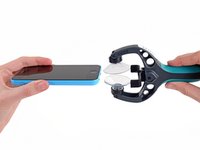
Close the handle on the iSclack, opening the suction-cup jaws.
-
Place the bottom of your iPhone in between the suction cups, against the plastic depth gauge.
-
The top suction cup should rest just above the home button.
-
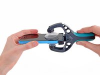
Open the handles to close the jaws of the iSclack. Center the suction cups and press them firmly onto the top and bottom of the iPhone.
-
-
-
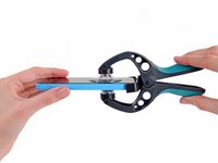
Hold onto your iPhone securely and close the handle of the iSclack to separate the suction cups, pulling the front panel up from the rear case.
-
The iSclack is designed to safely open your iPhone just enough to separate the pieces, but not enough to damage any cables.
-
Skip the next three steps and continue on to Step 8.
-
-
-
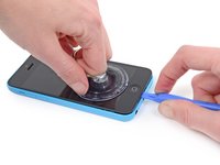
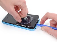
Press a suction cup onto the screen, just above the home button.
-
-
-
While holding the iPhone down with one hand, pull up on the suction cup to slightly separate the front panel assembly from the rear case.
-
With a plastic opening tool, begin to gently pry the rear case down, away from the display assembly, while you pull up with the suction cup.
-
-
-
Pull the plastic nub to release the vacuum seal on the suction cup.
-
Remove the suction cup from the display assembly.
-
-
-
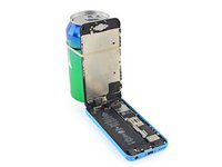
Lift the home button end of the front panel up to gain access to the connectors near the top of the phone.
-
Open the display to about a 90º angle, and lean it against something to keep it propped up while you're working on the phone.
-
In a pinch, you can use an unopened canned beverage to hold the display.
-
Add a rubber band to keep the display securely in place while you work. This prevents undue strain on the display cables.
-
-
-
-
Remove the two 1.6 mm Phillips #000 screws securing the metal battery connector bracket to the logic board.
-
-
-
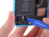
Use a spudger or a clean fingernail to gently pry the battery connector up from its socket on the logic board.
-
-
-
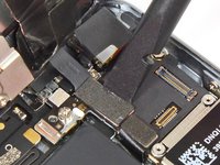
Remove the following Phillips #000 screws securing the front panel assembly cable bracket to the logic board:
-
Two 1.3 mm screws
-
One 1.7 mm screw
-
One 3.25 mm screw
-
-
-
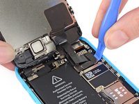
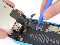
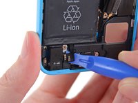
Use a plastic opening tool or a fingernail to disconnect the front-facing camera and sensor cable connector.
-
-
-
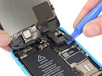
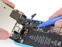
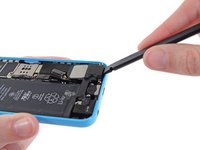
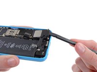
Use a plastic opening tool or a fingernail to disconnect the LCD cable connector.
-
-
-
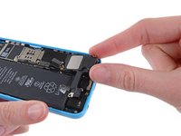
Remove the front panel assembly from the rear case.
-
-
-
Use a plastic opening tool to peel the home button spring contact cable up from the speaker enclosure.
-
-
-
Remove the following screws securing the speaker enclosure to the rear case:
-
Two 2.7 mm Phillips #000 screws
-
One 2.2 mm Phillips #000 screw
-
-
-
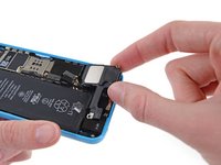
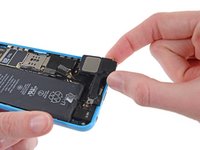
Use the flat end of a spudger to gently pry the speaker enclosure up from the rear case.
-
-
-
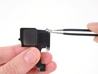
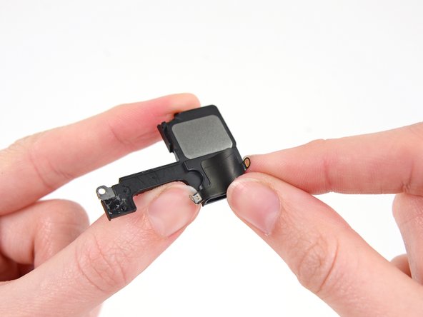
The far right screw hole on the speaker has a contact bracket wrapped around it. Remove it and note the orientation for reassembly.
-
-
-
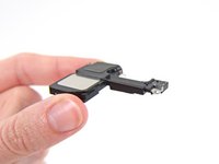
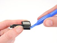
Use a plastic opening tool to lift the sticker from the speaker.
-
Peel up and remove the sticker.
-


To reassemble your device, follow these instructions in reverse order.
Отменить: Я не выполнил это руководство.
36 человек успешно провели ремонт по этому руководству.


5 Комментарии к руководству
Speaker doesn't work even after replacing using this guide, any idea what can be wrong? many thanks
Same here. Speaker went out. Replaced it with a new one from an Amazon seller, and still nothing. It's like I didn't do anything.
Rest of the phone works perfectly.
I just did this replacement today and had the same problem as the other posts. However what I figured out was that the speaker is powered through contact on the back side. I applied some pressure to that area (this is mostly likely bad for the screen, so try at your own risk) to the speaker area and surprise it worked. A hacky fix was to put a piece of folded up paper on top of the speaker to create the contact. I do not recommend this fix, but it help solidify the actual cause.
Hope this helps
ayechonk merci pour le tips, c'est bien un faux contact, en appuyant un peu j'ai le son, je vais testé le coup de la cale.
Does anyone know what's the actual voltage needed by the loudspeaker to work? I've tested it out the continuity of the loudspeakers (both the original on the replacing part) and they seem to work just fine, otherwise the output voltage from the motherboard on the contact while playing some music, swings quickly from 0 to 1mV.