Введение
Use this guide to remove or replace a faulty logic board in your iPhone 6.
It's important to note that each iPhone's logic board and Touch ID fingerprint sensor are paired at the factory, so replacing the logic board will disable Touch ID unless you also install a replacement home button that has been properly paired to your new logic board.
You can also use this guide to replace the Upper Cable Bracket.
Выберете то, что вам нужно
-
-
-
Power off your iPhone before beginning disassembly.
-
Remove the two 3.6 mm-long P2 Pentalobe screws next to the Lightning connector.
 Спросите у FixBot
-
-
-
-
Инструмент, используемый на этом этапе:Clampy - Anti-Clamp$24.95
-
Pull the blue handle backwards to unlock the Anti-Clamp's arms.
-
Slide the arms over either the left or right edge of your iPhone.
-
Position the suction cups near the bottom edge of the iPhone just above the home button—one on the front, and one on the back.
-
Squeeze the cups together to apply suction to the desired area.
-
-
-
Pull the blue handle forwards to lock the arms.
-
Turn the handle clockwise 360 degrees or until the cups start to stretch.
-
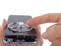
Insert an opening pick under the screen when the Anti-Clamp creates a large enough gap.
-
Skip the next three steps.
-
-
-
-
Инструмент, используемый на этом этапе:Clampy - Anti-Clamp$24.95
-
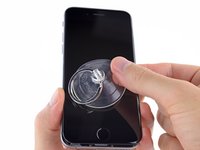
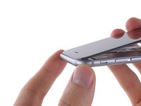
If you don't have an Anti-Clamp, use a single suction cup to lift the front panel:
-
Press a suction cup onto the screen, just above the home button.
-
-
-
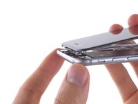
While holding the iPhone down with one hand, pull up on the suction cup to slightly separate the front panel assembly from the rear case.
-
Using a plastic opening tool, begin to gently pry the rear case down, away from the display assembly, while continuing to pull up with the suction cup.
-
-
-
Pull the plastic nub to release the vacuum seal on the suction cup.
-
Remove the suction cup from the display assembly.
-
-
-
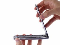
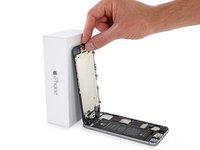
Open the iPhone by swinging the home button end of the front panel assembly away from the rear case, using the top of the phone as a hinge.
-
-
-
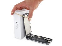
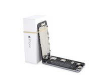
Open the display to about a 90º angle, and lean it against something to keep it propped up while you're working on the phone.
-
Add a rubber band to keep the display securely in place while you work. This prevents undue strain on the display cables.
-
-
Инструмент, используемый на этом этапе:Magnetic Project Mat$19.95
-
Remove the following Phillips screws from the battery connector bracket:
-
One 2.2 mm screw
-
One 3.2 mm screw
-
-
-
Use a plastic opening tool to gently pry the battery connector up from its socket on the logic board.
-
-
-
Remove the following five Phillips screws securing the front panel assembly cable bracket:
-
Three 1.2 mm screws
-
One 1.7 mm screw
-
One 3.1 mm screw
-
-
-
Remove the front panel assembly cable bracket from the logic board.
-
-
-
-
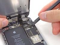
Use a spudger or a fingernail to disconnect the front-facing camera and sensor cable connector.
-
-
-
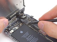
Use a spudger or a fingernail to disconnect the home button cable connector.
-
-
-
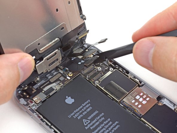
Use a spudger or a fingernail to disconnect the display data cable connector.
-
-
-
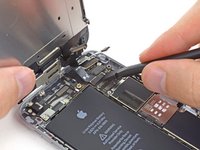
Use the flat end of a spudger to disconnect the digitizer cable connector.
-
-
-
Remove the front panel assembly from the rear case.
-
-
-
-
-
Insert a SIM card eject tool or a paperclip into the small hole in the SIM card tray.
-
Press to eject the tray.
-
-
-
-
-
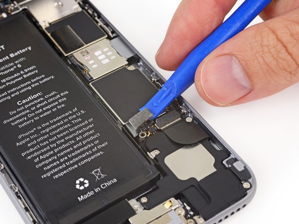
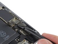
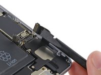
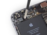
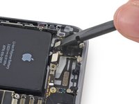
Use the flat end of a spudger to disconnect the Lightning connector assembly cable and fold it out of the way of the speaker.
-
-
-
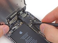
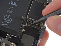
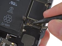
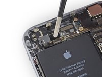
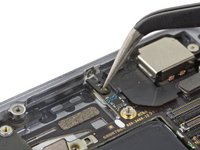
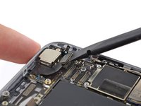
Use the point of a spudger to lift the antenna cable connector up off of its socket on the logic board.
-
-
-
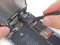
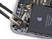
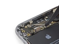
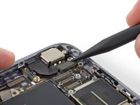
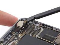
Remove the following Phillips screws from the upper cable bracket:
-
One 2.9 mm screw
-
One 2.2 mm screw
-
-
-
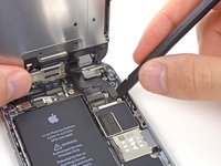
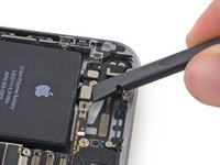
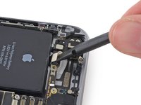
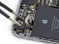
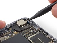
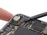
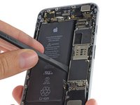
Use the flat end of a spudger to lift the power button and flash assembly cable connector up off of its socket.
-
Lift the volume control cable connector up out of its socket on the logic board.
-
-
-
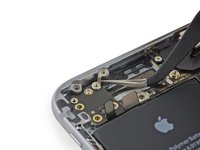
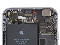
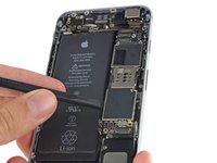
Remove the following four Phillips screws from the Wi-Fi antenna:
-
One 1.5 mm screw
-
One 1.4 mm screw
-
Two 2.1 mm screws
-
-
Инструмент, используемый на этом этапе:Tweezers$4.99
-
Remove the Wi-Fi antenna from the iPhone.
-
-
-
Remove the two 1.6 mm Phillips screws from the grounding bracket.
-
-
-
Remove the following Phillips screws securing the angled logic board bracket.
-
One 2.6 mm screw
-
One 1.3 mm screw, located horizontally in the upper sidewall of the iPhone.
-
-
-
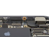
Remove the single 1.2 mm Phillips screw securing the antenna interconnect cable to the logic board.
-
-
-
Use the point of a spudger to fold the antenna interconnect cable up out of the way of the logic board.
-
-
-
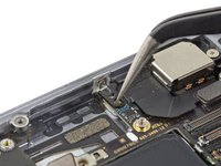
Use the flat end of a spudger to lift the camera cable connector straight up out of its socket on the logic board.
-
Fold the camera cable up out of the way of the logic board.
-
-
Инструмент, используемый на этом этапе:Standoff Screwdriver for iPhones$5.49
-
Remove the following screws securing the logic board to the rear case:
-
Two 1.9 mm Phillips screws
-
One 2.3 mm standoff screw
-
-
-
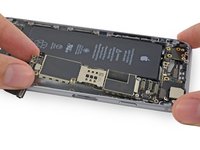
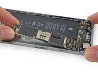
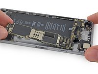
Use the flat end of a spudger to lift the battery connector end of the logic board up slightly, just enough to grab with your fingers.
-
-
-
Lift the battery connector end of the logic board and pull it up and out of the rear case.
-
-


To reassemble your device, follow these instructions in reverse order.
Отменить: Я не выполнил это руководство.
663 человек успешно провели ремонт по этому руководству.


124 Комментарии к руководству
is there a way to swap only the memory component instead of the whole thing?
Yes, you can, but you will need to have some serious soldering skills. But in theory you can replace the memory chip with another memory chip that has been reprogrammed to fit your phone's serial number.
Anyone an idea, where I can find the logic board?
have you found one?
http://www.powerbookmedic.com/xcart1/hom...
I buy my Parts here