Введение
This is a guide for replacing the microphone on the Fusion5 5.5 Gen II device if the component appears to be damaged.
To determine if you need to replace your microphone, read this troubleshooting page before you go over this guide’s steps.
Before you disassemble your device, be sure to power off your device and ground yourself.
This guide requires soldering, so be well-informed on soldering safety before you attempt this guide’s steps. If you need any assistance on soldering, check out this existing guide on “How To Solder and Desolder Connections”.
Please refer to the EPA website to know how to properly dispose of any electronic waste.
Выберете то, что вам нужно
-
-
Hold the device with the screen facing away from you and the back of the device facing you.
-
Locate the groove at the bottom corner of the device.
-
Begin prying the back cover of the device off from the groove and working your way around the outside edges of the device.
 Спросите у FixBot
-
-
-
Remove the six 3mm Phillips #00 screws securing the lower back frame to the device.
-
Slide the lower back frame away, revealing the microphone and the board that it is connected to.
-
-
-
Инструмент, используемый на этом этапе:Tweezers$4.99
-
Using the tweezers, grasp the microphone and remove it from its socket on the device.
-
Straighten out the wires to make the next step easier.
-
-
-
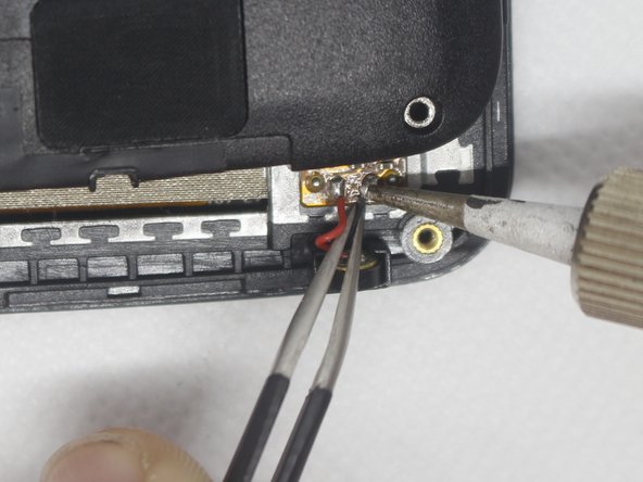
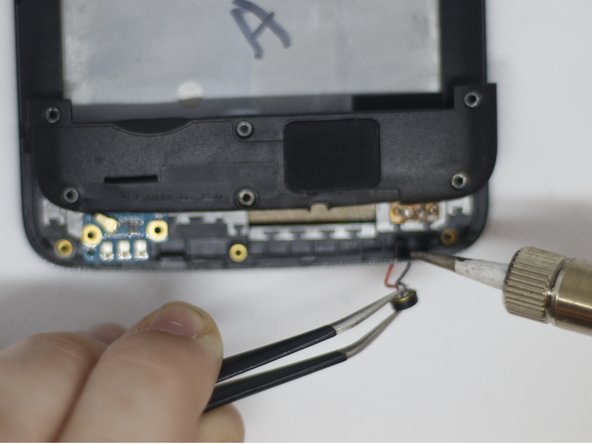
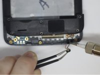
Using the tweezers and soldering iron, remove the red and black wires from the circuit board.
-


To reassemble your device, follow these instructions in reverse order.

Команда

Embry-Riddle Aeronautical University, Team S8-G1, Salas Fall 2019 Участник Embry-Riddle Aeronautical University, Team S8-G1, Salas Fall 2019
ERAU-SALAS-F19S8G1
4 членов
Автор 21 руководств
