Введение
Use this guide to replace the motherboard in an Xbox Series X.
You can also use this guide to reapply thermal paste in your Xbox.
Before you begin, completely power down and unplug all cables from your console. Remember to follow general electrostatic discharge (ESD) safety procedures while repairing the console.
Выберете то, что вам нужно
-
-
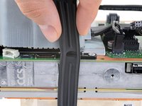
Use a pair of tweezers to remove the sticker hiding the first screw on the back panel, near the base.
-
-
-
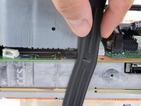
Use a pair of blunt tweezers to peel back the large sticker on the back panel to reveal the second screw.
-
-
Инструмент, используемый на этом этапе:Magnetic Project Mat$19.95
-
Use a T8 Torx driver to remove the two 7.4 mm‑long screws securing the back panel.
-
-
-
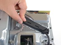
Insert the flat end of a spudger into the gap between the back panel and the shell, near the left side of the base.
-
Pry up the back panel to release it from the locking clips.
-
-
-
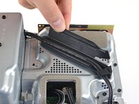
Insert the flat end of a spudger into the gap between the back panel and the shell, near the right side of the base.
-
Pry up the back panel to release it from the locking clips.
-
-
-
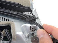
Grip the back panel at the opening you just created and pull it up and away from the shell to unclip the long edges.
-
-
-
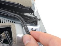
Tilt the back panel up and pull it away from the top edge of the shell to release it from the gap.
-
Remove the back panel.
-
-
-
Use a T8 Torx driver to remove the three screws securing the fan to the center chassis:
-
One 10.5 mm pancake screw
-
Two 8.8 mm screws
are there any 10.5mm wide head screw for the xbox fan for sale because i need a replacement because i accidentally broke mine
If the 10.5 mm screw isn’t budging, use some pliers to loosen it
-
-
Инструмент, используемый на этом этапе:Tweezers$4.99
-
Use your fingers or a pair of blunt tweezers to grip the edges of the fan cable connector, and pull up to disconnect it from the center chassis.
But don’t pull the connectors with tweezers because you will inevitably still damage the cable as you have no grip on the connector and the tweezers will slip.
-
-
-
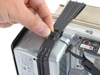
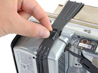
Use the flat end of a spudger to lift up on the locking tab holding the base to the shell.
-
-
-
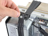
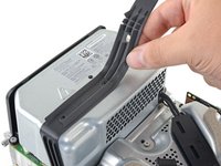
Grip the base and rotate it counterclockwise to unlock it from the shell.
-
Remove the base.
had trouble getting the base off, what worked for me is setting the console on the table sitting on the base and turning the whole console while pushing down.
-
-
-
Use a T8 Torx driver to remove the two 8.8 mm screws securing the optical drive's vibration isolator to the shell: one on the base and one on the top of the isolator.
-
-
-
Lift up the optical drive's vibration isolator to remove it.
-
-
Инструмент, используемый на этом этапе:Tweezers$4.99
-
Use a pair of blunt tweezers to grip the edges of the optical drive power connector and pull up to disconnect it from the optical drive.
-
Use your fingers to pull up and disconnect the data cable from the optical drive.
Once again, DO NOT use tweezers to pull these connectors out. That’s a great way to slip and damage something.
I managed to get the power connector unplugged, but the data cable just refuses to move. I've used quite a bit of force, and using any more feels like I would damage it. I have no clue on how to get it out safely :(
Try to "walk" the connector out: pry up one side, then the other. Best of luck!
-
-
-
Grip the top edge of the optical drive and pull it out of its slot in the shell to remove it.
-
-
-
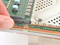
Use the flat end of a spudger to flip open the metal locking tab on the USB port ribbon cable.
-
-
-
Use a pair of tweezers to pull up on the black plastic pull tab to disconnect the USB port cable.
The silver ribbon cable is glued down to the center chassis, so only pulling on the black plastic pull tab will result in it pulling free from the cable as that tab is only glued to the cable.
Better to heat the silver ribbon cable's adhesive with a hair dryer, separate the cable from the center chassis, and then pull the cable from the connector using the black plastic pull tab.
-
-
-
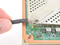
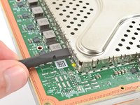
Use the pointed end of a spudger to depress the metal tab on the side of the power button cable's board connector.
-
With the metal tab depressed, use a pair of tweezers to pull up on the pull tab to disconnect the power button cable from the center chassis.
I broke this connector during disassembly. Is there a part number I can use to get a replacement on Mouser or Digikey?
I broke this connector during disassembly too. Where can I get this connector?
the manufacturer of connectors in series x is I-PEX. exact part number (as far as I'm not mistaken) 20535-010E-02 EVAFLEX 5-VS. 0.5mm pin spacing (10pin connector). a possible rescue may be to desolder the connector from the switch board and solder it permanently there.
How do I purchase this from their website?
I have these connectors. Baycroc@fedtel.net
Would we be able to order them from you directly
Yes would we be able to order these connectors directly from you?
There is no black pull tab on mine😬. How am I supposed to pull it safely?
-
-
-
Use a T8 Torx driver to remove the three 7.4 mm screws securing the center chassis assembly to the shell.
-
-
-
-
Gently peel the taped USB port ribbon cable off of the heatsink.
-
-
-
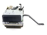
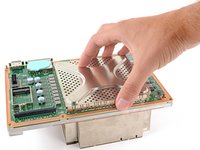
Grip the center chassis and pull it towards the green fan grille at the top of the shell, uncoupling the guide pegs from the shell.
-
Lift out the center chassis assembly to remove it from the shell.
-
-
-
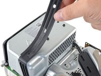
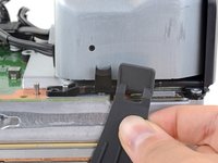
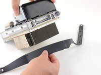
Unlatch the chassis strap from the right side of the power supply.
-
-
-
Pull the chassis strap over and off of the power supply.
-
Once the strap is off of the power supply, set the loose section to the side.
-
-
-
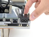
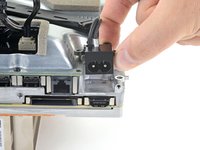
Use a T8 Torx driver to remove the three screws securing the power cable port to the chassis:
-
Two 13.1 mm screws
-
One 35 mm screw
-
-
-
Unlatch and open the lid on the power cable's plastic guide.
-
-
-
Use a T8 Torx driver to remove the 8.8 mm screw securing the power supply corner cover.
-
-
Инструмент, используемый на этом этапе:Tweezers$4.99
-
Use your fingers or a pair of tweezers to lift and remove the power supply corner cover.
-
-
-
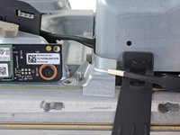
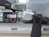
Use a T8 Torx driver to remove the three 9.6 mm screws securing the accessory antenna board to the center chassis.
-
-
-
Grip the antenna board and pull it directly away from the center chassis to disconnect it.
Is this is WIFI Antenna Board that required to replaced if there is a issue with WIFI non-detection ?
-
-
-
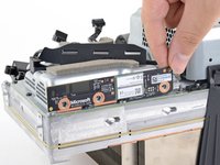
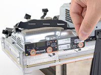
Use a T8 Torx driver to remove the nine screws securing the board shield:
-
Six 8.8 mm black screws
-
Two 35 mm silver screws
-
One 13.1 mm silver screw
-
-
-
Disconnect the chassis strap from the locking tabs on either side of the power supply.
-
-
-
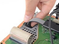
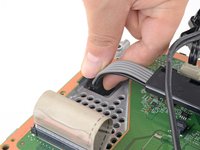
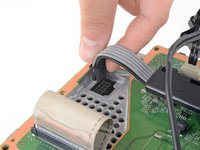
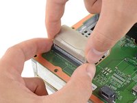
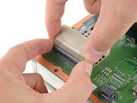
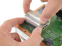
Grip and compress the locking tab on the 10-pin power connector.
-
While compressing the locking tab, lift the connector straight up to disconnect it from the board.
-
-
-
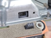
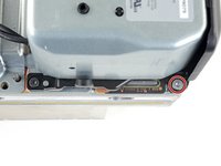
Grip the base of the interconnect cable connector with your fingers.
-
Depress each side of the connector to unlock the cable locking tabs.
-
With the locking tabs depressed, grip the edges of the interconnect cable and pull it straight out of the connector to disconnect it.
Bij deze had ik een andere connector . Ik had in het midden een tab dat ik moest indrukken en toen kwam de kabel met een zwarte connector uit een grijze connector . Ik heb de 20 jaar editie Xbox X .
There is a variant of this connection that has the locking tab on the front of the connector.
-
-
-
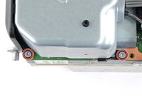
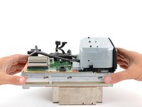
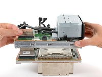
Use a T8 Torx driver to remove the three 35 mm‑long silver screws from the power supply—leave the fourth black screw in place.
-
-
-
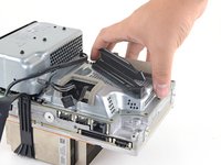
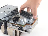
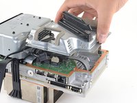
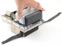
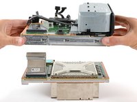
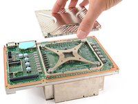
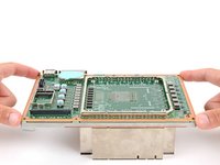
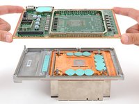
Grip the edges of the center chassis (not the power supply) and lift it off of the motherboard and heatsink assembly, routing the interconnect cable through its cutout.
-
-
-
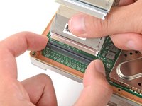
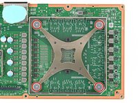
Use the flat end of a spudger to pry up the edges of the metal SSD shield.
-
Remove the SSD shield.
-
-
-
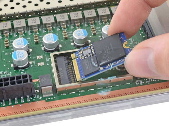
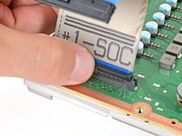
Use a T8 Torx driver to remove the 5.2 mm screw securing the SSD.
-
-
-
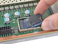
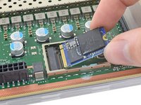
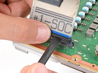
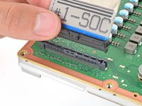
Grip the end of the SSD and pull it away from its M.2 board connector to remove it.
I use SABRENT Tool-Free USB Type-C Dual Docking Station for PCIe NVMe M.2 SSDs with Offline Cloning Function (EC-SSD2).
my ssd is unfortunately broken and cloning from another series x nvme didn't work, the power led lights up briefly and goes off again and that's it
It is firmware locked by microsoft, you must go to them to change the ssd
Imagine going through all this, just to find out the console doesn't even support a full-sized NVMe drive.
48 steps to replace the SSD? Smh
At least the primary storage is replaceable at all, unlike the PS5.
Tyler -
Make it daunting enough and people would rather go to the manufacturer to do it.. we need better placement for this. Not only for easier replacement but better cooling
If you want a larger drive with better cooling that should be on the external storage card, not the internal drive.
Tyler -
Absolutely terrible from microsoft. Much like their surface pro devices.
Make a simple task as hard as possible so that people will just buy a new device instead of a simple and cheap fix.
Boo microsoft
The storage replacement process is better on the Xbox Series consoles than the PS5 in every way. To replace the Xbox external drive you just slide it out, don't need a screw driver or even turn off the console. The PS5 requires tools. The internal drive on Xbox can be replaced as shown above. The PS5 internal drive is soldered to the motherboard. So boo Sony.
Tyler -
There is a partition key that has to be copied over form the original ssd if not damaged. Will have to have a nvme reader and use disk management software. Then after will need to put into safe mode and load the osu1 update for xbox then be set. Though if can't get the partition key it bricks it to where turns on then off. If only there was a master key to initialize the console then run the osu1 for the software.
What's the ssd model? Maybe hook up to a pc?
-
-
-
Grip the base of the interconnect cable connector with your fingers.
-
Depress each side of the connector to unlock the cable locking tabs.
-
With the locking tabs depressed, grip the edges of the interconnect cable and pull it straight out of the connector to disconnect it.
-
Remove the interconnect cable.
-
-
-
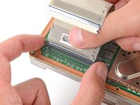
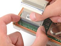
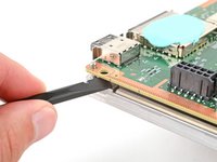
Pinch the locking tab on the interconnect cable on the motherboard and use the flat end of a spudger to disengage the clip.
-
Use your fingers to pull the connector straight up and out of its socket.
-
-
-
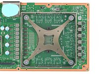
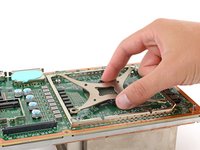
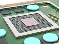
Use the flat end of a spudger to pry up the edges of the large metal shield in the center of the motherboard.
-
-
-
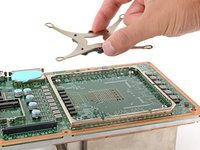
Use a T8 Torx driver to remove the four 12.3 mm‑long APU tension bracket screws.
-
-
-
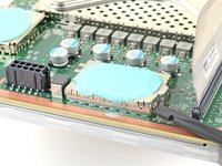
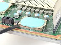
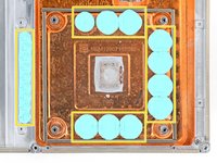
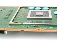
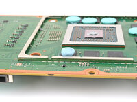
Check the condition of the thermal putty—it'll be on the heatsink and/or the motherboard.
-
If any pieces are damaged or dried out, follow the next four steps to remove and replace them.
-
If you're only replacing the thermal paste, skip to this step.
-
-
-
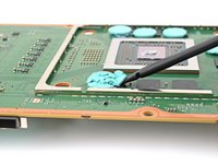
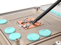
Use the flat end of a spudger to scrape off the damaged or deteriorated thermal pad.
-
-
Инструмент, используемый на этом этапе:Cotton Swabs$4.99
-
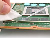
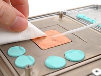
Use isopropyl alcohol (>90%) and a lint-free microfiber cloth to remove any thermal putty residue.
-
-
-
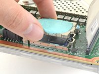
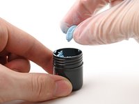
Grab a small piece of thermal putty. Refer to the size of the thermal pad you're replacing for how much you need.
-
-
-
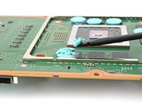
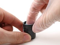
Roll the thermal putty into a ball.
-
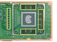
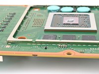
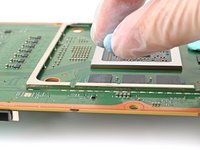
Place the thermal putty where the damaged thermal pad was, making sure it's centered over the component—in this case a memory chip.
-
Optionally, you can use the flat end of a spudger (or an included applicator) to spread the thermal putty over the surface of the component.
-
-
Инструмент, используемый на этом этапе:Cotton Swabs$4.99
-
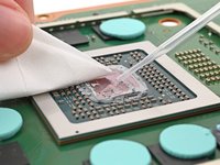
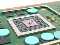
Apply a few drops of isopropyl alcohol (>90%) to the processor and use a coffee filter or a lint-free cloth to wipe away any residue.
-
-
-
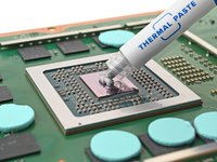
Apply a small bead of thermal paste to the center of the APU.
-


To reassemble your device, follow these instructions in reverse order.
Take your e-waste to an R2 or e-Stewards certified recycler.
Repair didn’t go as planned? Try some basic troubleshooting, or ask our Xbox Series X Answers community for help.
To reassemble your device, follow these instructions in reverse order.
Take your e-waste to an R2 or e-Stewards certified recycler.
Repair didn’t go as planned? Try some basic troubleshooting, or ask our Xbox Series X Answers community for help.
Отменить: Я не выполнил это руководство.
21 человек успешно провели ремонт по этому руководству.


4 Комментариев
There are five completely unnecessary steps in this guide all centered around removing the PSU and the part under it that don't need to be done in order to remove the motherboard/heatsink. You can cut out steps 38, 39, 41, 42 and 43 on step 40 you only need to remove the three 35mm screws to complete the step. As long as you complete the rest of the guide the top comes away without issue.
Hi Alex! The guide has been updated and any unnecessary steps have been removed. Thank you for the helpful information!
Thanks....... I just had one apart and skipped those steps with no problems.
If you replace the motherboard will the disk drive still work?