Перейти к основному содержанию

In-Place Fan Cover Removal

Выберете то, что вам нужно

  1. In-Place Fan Cover Removal, Remove fan bumper: шаг 1, изображение 1 из 3 In-Place Fan Cover Removal, Remove fan bumper: шаг 1, изображение 2 из 3 In-Place Fan Cover Removal, Remove fan bumper: шаг 1, изображение 3 из 3
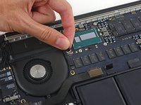
    • Carefully remove the rubber fan bumper from the edge of the heat sink.

    • The bumper is gently held in place by the lips in the third image which wrap under the heat sink. There is no adhesive, so removal and reseating should be easy.

  2. In-Place Fan Cover Removal, iSight Cable: шаг 2, изображение 1 из 2 In-Place Fan Cover Removal, iSight Cable: шаг 2, изображение 2 из 2
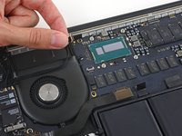
    • Use the tip of a spudger to push on either side of the the iSight camera cable connector to walk it out of its socket on the logic board.

    • The cable connector is small and delicate, so make sure to nudge it out a little bit at a time from each side, alternating until it is fully out. A spudger or tweezers are ideal for this.

  3. In-Place Fan Cover Removal: шаг 3, изображение 1 из 2 In-Place Fan Cover Removal: шаг 3, изображение 2 из 2
    • Peel the iSight camera cable off the fan housing to fold it out of the way.

    • You can optionally use hot air to soften the adhesive and/or a spudger to help separate the cable from the fan housing.

  4. In-Place Fan Cover Removal, Disconnect I/O board cable: шаг 4, изображение 1 из 2 In-Place Fan Cover Removal, Disconnect I/O board cable: шаг 4, изображение 2 из 2
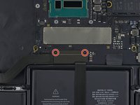
    • One of the screws holding the top shell of the fan assembly is hidden just behind the I/O board cable.

    • Remove the two 2.1 mm T5 Torx screws securing the I/O board cable bracket to the logic board.

    • Remove the I/O board cable bracket.

  5. In-Place Fan Cover Removal: шаг 5, изображение 1 из 2 In-Place Fan Cover Removal: шаг 5, изображение 2 из 2
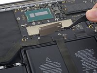
    • Use the flat end of a spudger to pop the I/O board connector straight up off its socket on the logic board.

    • Be careful to only pry up on the I/O board cable, not on the socket itself or you risk damaging your logic board.

  6. In-Place Fan Cover Removal: шаг 6, изображение 1 из 2 In-Place Fan Cover Removal: шаг 6, изображение 2 из 2
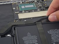
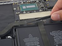
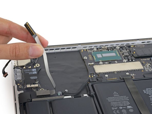
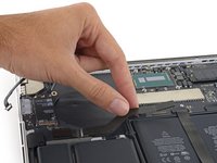
    • Lift the logic board end of the I/O board cable straight up to bend it out of the way.

    • To avoid damage to the cable, fold only at the bend in the I/O board end of the cable. It will only be in the way momentarily, so don't try forcing it to stay.

  7. In-Place Fan Cover Removal: шаг 7, изображение 1 из 1
    • Remove the following screws securing the fan assembly cover to the rest of the assembly:

    • One 5.0 mm T5 Torx screw.

    • This screw holds the upper case, main fan assembly, and fan assembly together, and so must be removed.

    • 3 Phillips #000 screws.

    • The bottom right screw is just under the I/O board cable, and will be visible after it has been lifted out of the way.

Заключение

To reassemble your device, follow these instructions in reverse order.

3 участников успешно повторили данное руководство.

Stefan Countryman

Участник с: 11/24/17

517 Репутация

Автор 2 руководств

0 Комментариев

Добавить комментарий

Просмотр статистики:

За последние 24часов: 0

За последние 7 дней: 11

За последние 30 дней: 52

За всё время: 860