
iPad Mini 2 LTE Logic Board Replacement

Введение
Перейти к шагу 1Use this guide to replace a faulty logic board in your iPad Mini 2 LTE.
Parts of this guide were shot with a Wi-Fi model and as such the internals may look slightly different from the LTE model. The procedure is the same for both models except where noted.
Выберете то, что вам нужно


-
-
Heat the iOpener for thirty seconds.
-
Throughout the repair procedure, as the iOpener cools, reheat it in the microwave for an additional thirty seconds at a time.
-
-
-
Remove the iOpener from the microwave, holding it by one of the two flat ends to avoid the hot center.
-
-
-
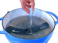
Fill a pot or pan with enough water to fully submerge an iOpener.
-
Heat the water to a boil. Turn off the heat.
-
Place an iOpener into the hot water for 2-3 minutes. Make sure the iOpener is fully submerged in the water.
-
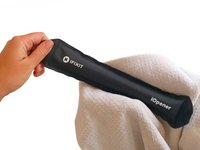
Use tongs to extract the heated iOpener from the hot water.
-
Thoroughly dry the iOpener with a towel.
-
Your iOpener is ready for use! If you need to reheat the iOpener, heat the water to a boil, turn off the heat, and place the iOpener in the water for 2-3 minutes.
-
-
-
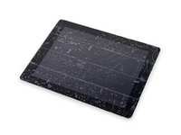
If your display glass is cracked, keep further breakage contained and prevent bodily harm during your repair by taping the glass.
-
Lay overlapping strips of clear packing tape over the iPad's display until the whole face is covered.
-
Do your best to follow the rest of the guide as described. However, once the glass is broken, it will likely continue to crack as you work, and you may need to use a metal prying tool to scoop the glass out.
-
-
-
Handling it by the tab, place the heated iOpener on the side of the iPad to the left of the home button assembly.
-
Let the iOpener sit for about five minutes to soften the adhesive beneath the glass.
-
-
-
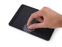
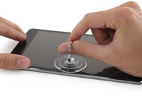
Carefully place a suction cup halfway up the heated side.
-
Be sure the cup is completely flat on the screen to get a tight seal.
-
While holding the iPad down with one hand, pull up on the suction cup to slightly separate the front panel glass from from the rear case.
-
-
-
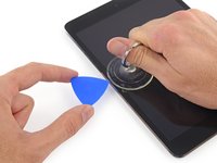
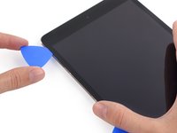
While holding the glass up with the suction cup, slide the point of an opening pick into the gap between the glass and body of the iPad.
-
Pull the suction cup's plastic nub to release the vacuum seal and remove the suction cup from the display assembly.
-
-
-
Reheat and reapply the iOpener.
-
Let it rest for a few minutes to reheat the left edge of the iPad.
-
-
-
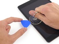
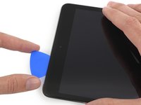
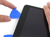
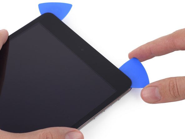
Place a second opening pick alongside the first and slide the pick down along the edge of the iPad, releasing the adhesive as you go.
-
-
-
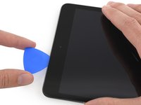
Continue moving the opening pick down the side of the display to release the adhesive.
-
If the opening pick gets stuck in the adhesive, "roll" the pick along the side of the iPad, continuing to release the adhesive.
-
-
-
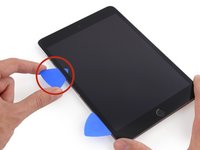
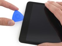
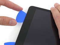
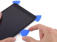
Take the first pick you inserted and slide it up toward the top corner of the iPad.
-
If you can see the tip of the opening pick through the front glass, don't panic—just pull the pick out a little bit. Most likely, everything will be fine, but try to avoid this as it may deposit adhesive on the front of the LCD that is difficult to clean off.
-
-
-
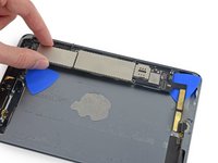
Reheat the iOpener and place it on the top edge of the iPad, over the front-facing camera.
-
-
-
Slide the opening pick around the top left corner of the iPad to separate the adhesive.
-
-
-
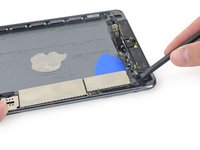
Slide the opening pick along the top edge of the iPad, stopping just before you reach the camera.
-
-
-
Pull the pick out slightly, and slide the very tip gently along the top of the front-facing camera section of the top edge.
-
-
-
Leave the opening pick in the iPad slightly past the front-facing camera.
-
Take a second pick and insert it to the left of the camera, where the first pick just was. Slide it back to the corner to completely cut any remaining adhesive.
-
Leave the second pick in place to prevent the corner adhesive from re-sealing as it cools.
-
-
-
Insert the previous pick deeper into the iPad and slide it away from the camera toward the corner.
-
-
-
Leave the three picks in the corners of the iPad to prevent re-adhering of the front panel adhesive.
-
Reheat the iOpener and place it on the remaining long side of the iPad—along the volume and lock buttons.
-
-
-
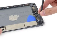
Slide the top right opening pick around the corner to fully release the top edge of the glass.
-
-
-
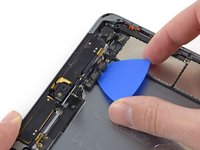
Insert a new opening pick and slide it to the middle of the right edge of the iPad, releasing the adhesive as you go.
-
-
-
Continue to slide the pick down the right edge of the iPad, releasing the adhesive.
-
-
-
Leave the opening picks in place and reheat the iOpener.
-
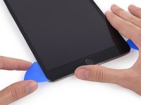
Set the reheated iOpener on the home button end of the iPad and let it rest for a few minutes to soften the adhesive beneath the glass.
-
-
-
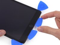
Slide the lower left pick to the lower left corner to cut the adhesive on that corner.
-
Leave the pick at the corner. Do not pry any farther, and do not remove the pick from the iPad.
-
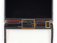
Antennas
-
Home button cavity
-
Digitizer cable
-
The following steps will direct you where to pry to avoid damage to these components. Only apply heat and pry where directed.
-
-
-
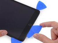
With a new pick, slice gently over the left-hand antenna, stopping before the home button.
-
Leave the pick in place before moving on.
-
-
-
Insert the tip of one last pick next to the previous step's pick, and slide it beneath the home button.
-
Insert the pick slightly deeper and work it back toward the home button.
-
-
-
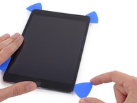
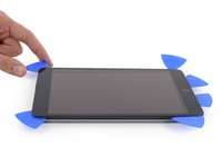
At the top of the iPad opposite the home button, you should have a pick lodged into each corner. Twist the picks to lift the glass slightly, separating the last of the adhesive along all four edges.
-
-
-
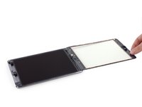
Once all of the adhesive has been separated, open the front glass like a page in a book and rest it on your workspace.
-
-
-
Rock the camera housing up on one edge to free it from the adhesive and remove it from the front panel.
-
Return the front-facing camera housing to its recess in the rear case.
-
-
Инструмент, используемый на этом этапе:Tweezers$4.99
-
Remove the following Phillips #00 screws securing the LCD:
-
Three 3.3 mm screws
-
One 4.5 mm screw
-
-
-
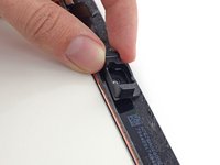
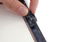
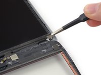
Insert the flat end of a spudger under the LCD between it and the LCD shield plate and lift gently.
-
-
-
Insert the spudger between the LCD and LCD shield plate and slide it to the far edge of the iPad.
-
-
-
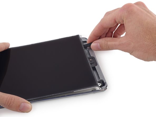
Hold the LCD with one hand, and the rear body of the iPad with the other.
-
Gently pull the LCD away from the speakers to separate the tape, being careful not to pull on the digitizer cable.
-
-
-
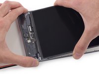
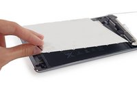
Flip the iPad LCD like a page in a book, lifting near the camera and turning it over the home button end of the rear case.
-
Lay the LCD on the front panel glass to allow access to the display cables.
-
-
-
-
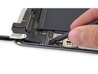
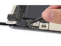
Slide the tip of a spudger between the LCD and the adhesive tabs to free the display.
-
Push gently between each of the two adhesive tabs; be careful not to damage any of the nearby cables.
-
-
-
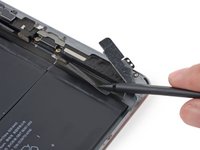
Use the flat end of a spudger to pry the LCD shield plate up and out of the iPad.
-
Remove the LCD shield plate.
-
-
-
Remove the following Phillips #00 screws from the display cable bracket:
-
One 2.7 mm screw
-
Two 1.4 mm screws
-
-
-
Use the flat tip of a spudger to gently lift the battery connector up off its socket on the logic board.
-
-
-
Remove the following Phillips #00 screws from the left antenna:
-
One 2.6 mm screw
-
Two 1.5 mm screws
-
-
-
Use the flat end of a spudger to loosen the foam adhesive securing the Wi-Fi antenna to the left speaker.
-
-
-
Use the flat end of a spudger to fold the wide left-hand piece of tape away from the left speaker.
-
-
-
Use the tip of a spudger to pry the antenna cable tape up from the rear case of the iPad.
-
Gently pull the antenna cable out of the way as you work along the piece of tape to free it and keep it from resealing.
-
-
-
Pull the wide tape toward the battery, applying constant force to peel it from the antenna cable lodged between it and the speaker.
-
Insert a plastic opening tool into the gap between the wide tape and the antenna cable, to break the adhesive connecting the two.
-
Slide the plastic opening tool along the length of the antenna cable to completely separate it from the piece of tape.
-
-
-
Remove the following Phillips #00 screws from the right antenna:
-
Three 1.5 mm screws
-
One 2.6 mm screw
-
-
-
Use the flat end of a spudger to cut the foam adhesive securing the antenna to the right speaker.
-
-
-
Pull the bend of the antenna cable out of the corner of the case.
-
Fold the antenna out of the way of the right speaker.
-
-
-
Remove the following Phillips #00 screws securing the right speaker to the rear case:
-
One 1.9 mm screw
-
One 1.7 mm screw with a large head
-
-
-
Push the speaker with the flat end of a spudger to begin sliding it out of its recess in the rear case.
-
-
-
Insert the tip of a spudger into the gap between the left speaker and the bottom left side of the rear case.
-
-
Инструмент, используемый на этом этапе:Tweezers$4.99
-
Use a set of tweezers to remove any tape covering the front-facing camera cable clips.
-
-
-
Use a plastic opening tool to fold the front-facing camera cable clips outward, away from the cable, to free the cable connector.
-
-
-
With the flat end of a spudger, lift the front-facing camera connector straight up off of its socket on the logic board.
-
Gently fold the front-facing camera cable towards the camera, moving it out of the way of the cable under it.
-
-
-
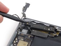
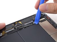
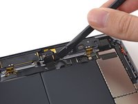
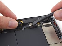
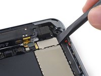
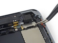
Use a set of tweezers to peel up the small piece of tape covering the headphone jack cable connector.
-
-
-
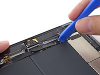
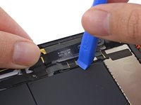
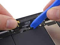
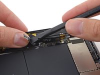
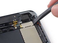
Use a plastic opening tool to fold the headphone jack cable clips outward, away from the cable, freeing the cable connector.
-
-
-
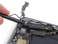
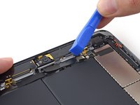
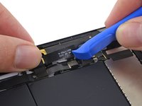
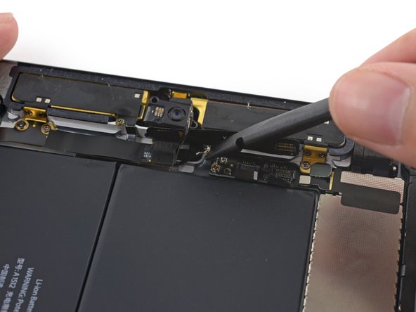
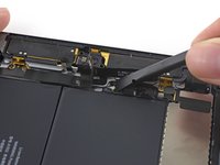
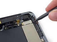
Pry the headphone jack cable's connector up from its socket on the logic board.
-
Lift the headphone jack cable up out of the way of the logic board.
-
-
-
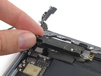
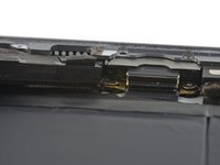
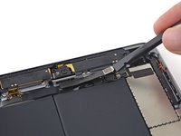
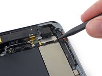
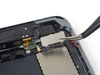
Use the flat end of a spudger to lift the top left antenna cable connector up from its socket on the logic board.
-
-
-
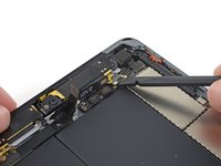
Use a plastic opening tool to push the rear-facing camera cable bracket to the left.
-
-
-
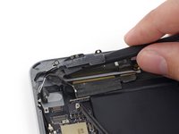
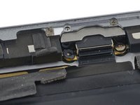
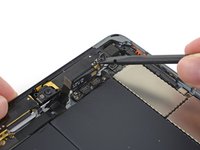
Remove the following three screws securing the upper right antenna to the rear case:
-
Two 1.3 mm #00 Phillips screws from the side of the antenna's socket.
-
One 1.8 mm #00 Phillips screw.
-
-
-
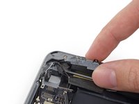
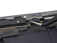
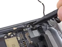
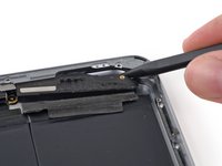
Use the flat end of a spudger to disconnect the upper right antenna's coaxial connector from the logic board.
-
Gently bend the cable tab up out of the way of the logic board.
-
-
-
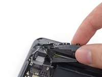
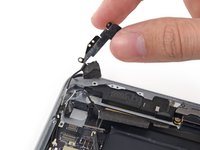
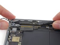
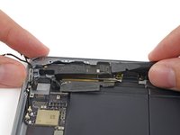
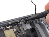
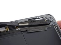
Use the flat end of a spudger to disconnect the upper right antenna connector.
-
Fold the cable up out of the way of the logic board.
-
-
-
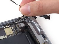
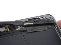
Use the flat end of a spudger to disconnect the rear-facing camera cable from its socket on the logic board.
-
Fold the rear-facing camera cable out of the way of the logic board.
-
-
-
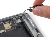
Remove the case button cable bracket from the iPad.
-
Use the flat end of a spudger to lift the case button cable connector straight up out of its socket on the logic board.
-
Fold the cable out of the way of the logic board.
-
-
-
Use the point of a spudger to lift the two antenna cable connectors straight up off of their sockets on the logic board.
-
-
-
Use the point of a spudger to pull the antenna cable clip toward the battery to allow access to the cables.
-
-
-
Remove the following Phillips #00 screws securing the left speaker to the rear case:
-
One 1.9 mm screw
-
One 1.7 mm screw
-
-
-
Insert the tip of a spudger into the gap between the left speaker and the bottom left side of the rear case.
-
Push the spudger in to slide the speaker out from its recess in the rear case.
-
-
-
Push from the Lightning connector end with the flat end of a spudger to free the speaker from the lip of the rear case.
-
-
-
Heat an iOpener and place it in the center of the back of the iPad case.
-
After a minute, reheat the iOpener and place it on the right side of the iPad, the side farthest from the camera.
-
-
Инструмент, используемый на этом этапе:Plastic Cards$2.99
-
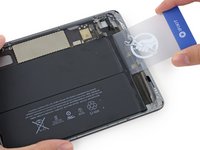
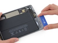
Insert a plastic card under the battery from the Lightning cable connector end of the iPad.
-
-
-
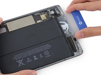
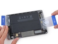
Remove the plastic card and insert it under the cell nearest the edge of the case.
-
-
-
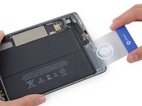
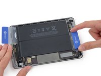
Insert a second plastic card beneath the battery on the logic board side near the front-facing camera.
-
-
-
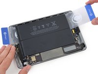
Remove the second card and reinsert it under the battery near the headphone jack.
-
-
-
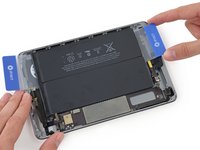
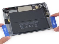
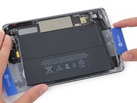
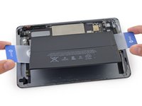
Grasp both cards and slowly pull the case-side cell of the battery up about two inches from the rear case.
-
Peel slowly and try not to bend the battery cell.
-
-
-
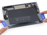
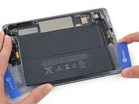
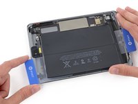
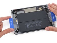
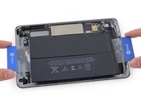
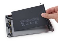
Grip both cards and use them to lift the battery up off the rear case.
-
Remove the battery from the iPad.
-
-
-
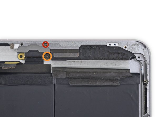
Use a set of tweezers to remove the small plastic covers on the screws in the Lightning connector housing.
-
-
-
Remove the two 2.8 mm Phillips #00 screws from the Lightning connector housing.
-
-
-
One under the upper component tab, and one under the Lightning connector ribbon cable.
-
-
-
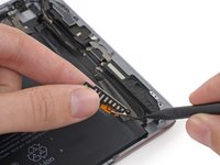
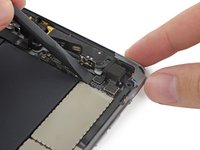
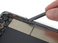
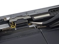
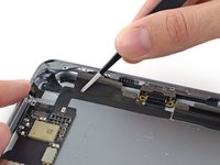
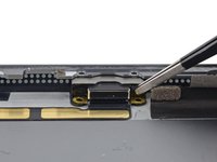
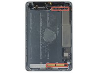
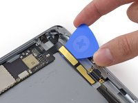
Carefully insert an opening pick under the ribbon cable near the Lighting connector housing.
-
Slide the opening pick toward the logic board, but stop half an inch from the bend in the cable.
-
-
-
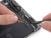
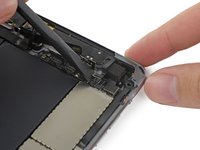
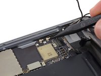
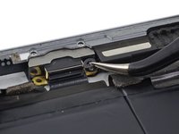
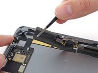
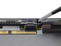
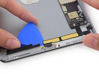
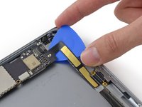
Reinsert the opening pick under the Lightning connector ribbon cable from the case-side edge.
-
Slide the pick along the Lightning connector ribbon cable and under the logic board.
-
Leave the pick under the Lightning connector cable to keep the adhesive separated.
-
-
-
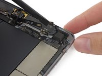
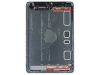
Reheat the iOpener and place it at the top of the rear case of the iPad for one minute.
-
-
-
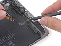
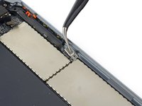
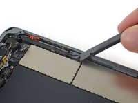
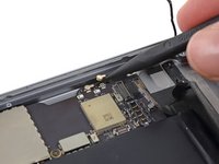
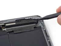
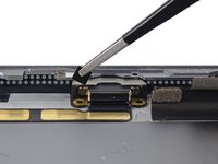
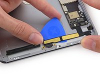
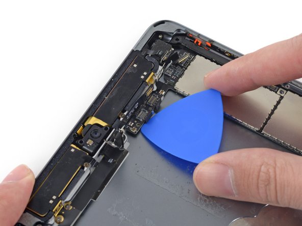
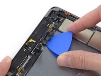
Carefully slide a second opening pick under the logic board to the right of the front-facing camera.
-
-
-
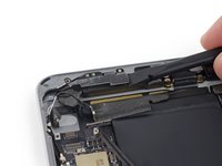
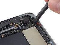
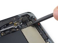
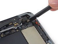
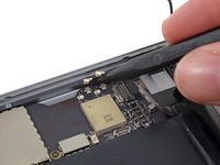
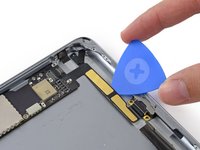
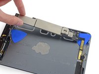
Carefully insert the flat end of a spudger between the rear-facing camera and the top of the logic board.
-
Pry the logic board up enough to grab it with your fingers.
-
-
-
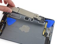
Lift the logic board by the camera end and gently pull the Lightning connector housing out of the rear case.
-
Remove the logic board from the iPad.
-


To reassemble your device, follow these instructions in reverse order.
To reassemble your device, follow these instructions in reverse order.
Отменить: Я не выполнил это руководство.
16 человек успешно провели ремонт по этому руководству.

