Введение
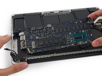
Use this guide to replace a faulty logic board.
Don't forget to follow our thermal paste application guide before you reinstall your heat sink.
Выберете то, что вам нужно
-
Инструмент, используемый на этом этапе:Magnetic Project Mat$16.96
-
Remove the following ten screws securing the lower case to the upper case:
-
Two 2.3 mm P5 Pentalobe screws
-
Eight 3.0 mm P5 Pentalobe screws
-
-
-
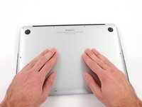
Wedge your fingers between the upper case and the lower case.
-
Gently pull the lower case away from the upper case to remove it.
-
-
-
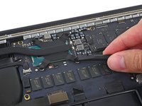
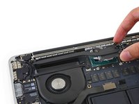
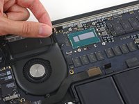
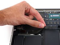
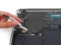
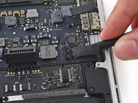
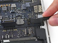
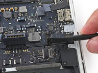
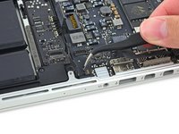
Use the flat end of a spudger to lift the battery connector straight up out of its socket on the logic board.
-
-
-
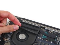
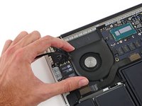
Carefully remove the rubber fan bumper from the edge of the heat sink.
-
-
-
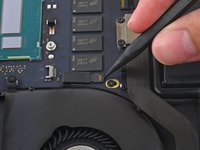
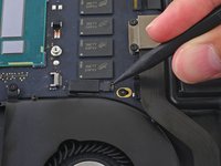
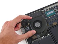
Use the flat end of a spudger to peel the four foam stickers off of the heat sink screws.
-
-
-
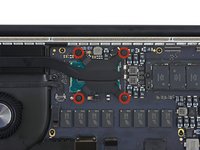
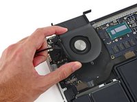
Remove the following screws securing the heat sink to the logic board:
-
Four 2.6 mm T5 screws
-
One 2.4 mm Phillips #000 screw
-
-
-
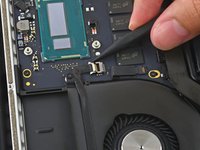
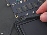
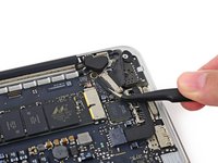
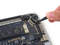
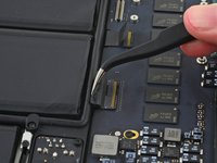
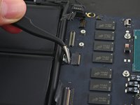
Use the tip of a spudger to push on either side of the the iSight camera cable connector to walk it out of its socket on the logic board.
-
-
-
-
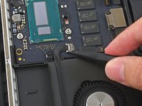
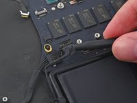
Use the tip of a spudger to flip the tab on the fan's ZIF connector.
-
Carefully pull the fan cable straight out of its socket.
-
-
-
Remove the following screws securing the fan to the upper case:
-
One 5.0 mm T5 Torx screw
-
Two 3.6 mm T5 Torx screws
-
-
-
Lift the end of the fan closest to the display hinge and remove the fan from the upper case.
-
-
-
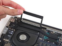
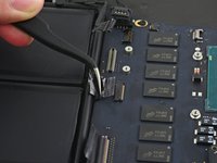
Remove the two 2.1 mm T5 Torx screws securing the I/O board cable bracket to the logic board.
-
Remove the I/O board cable bracket.
-
-
-
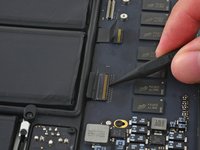
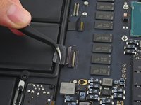
Use the flat end of a spudger to pop the I/O board connector straight up off its socket on the logic board.
-
-
-
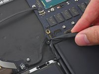
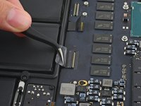
Lift the logic board end of the I/O board cable straight up to bend it out of the way.
-
-
-
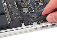
Use the tip of a spudger to lift the right speaker connector straight up out of its socket on the logic board.
-
-
-
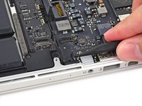
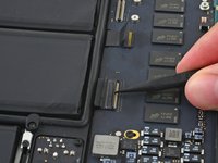
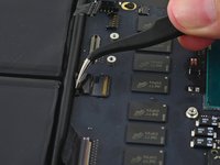
With the tip of a spudger, push on either side of the I/O board connector to walk it out of its socket on the logic board.
-
-
-
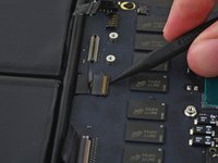
Use the flat end of a spudger to disconnect the keyboard backlight cable and bend it up out of the way of the logic board.
-
-
-
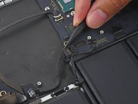
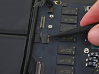
Grab the black plastic tab to flip the display cable connector open and pull it straight out of its socket on the logic board.
-
-
-
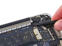
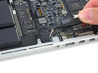
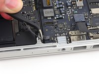
Carefully pull the DC-In board connector straight out of its socket on the logic board.
-
-
-
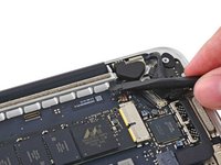
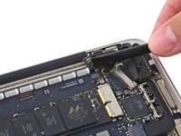
Wedge the flat end of a spudger under the left speaker cable near the connector and lift it straight up out of its socket and fold it out of the way.
-
-
-
Use the tip of a spudger to flip the retaining tab on the microphone cable ZIF connector.
-
Pull the microphone cable out of its socket on the logic board.
-
-
-
Remove the five 3.5 mm T5 Torx screws securing the logic board to the upper case.
-
-
-
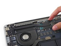
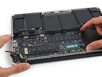
Lift the processor end of the logic board up slightly and pull it toward the fan recess to free the ports from the edge of the upper case.
-
Remove the logic board.
-
-
-
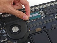
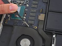
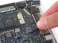
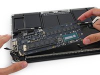
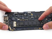
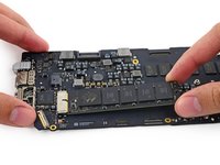
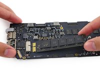
Remove the single 2.9 mm T5 Torx screw securing the SSD to the logic board.
-
-
-
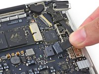
Lift the free end of the SSD up slightly and pull it straight out of its socket on the logic board.
-


To reassemble your device, follow these instructions in reverse order.
Отменить: Я не выполнил это руководство.
53 человек успешно провели ремонт по этому руководству.


10 Комментарии к руководству
Hi @sam !
I have a macbook pro 13" retina i5 2.6 8gb mid 2014 Model. A1502 and it has the damaged board.
In SAT, I changed it for 600 euros to replace it.
I have found a logicboard used for this same model A1502 (i7 3.0 Ghz 8Gb Ram) for half price and I would like to know if it is possible to replace it for this, or the mac will give me some problem when plugging a logicboard with different characteristics that the original?
Thanks for you support !
Was these ever answered?
Sam, thank you so much! Repair guide worked perfectly for removing logic board to clean corrosion after a water spill on the keyboard! Everything was exactly as picture and explained. I have two questions I was hoping Sam or someone else knowledgeable could answer.
1. Can/ should I replace the foam stickers from the heat sink screws (step 8)? If so, what kind of computer safe adhesive should I use to ensure that they stay in place?
2. Should the plastic cover adhered to the battery contact board in step 4 be replaced?