
iMac G5 20" Model A1145 Heat Sinks Replacement

Введение
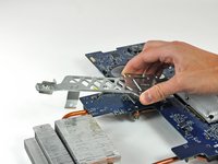
Перейти к шагу 1Use this guide to transfer the heat sinks to your new logic board.
Выберете то, что вам нужно
Инструменты


Показать больше…
-
-
Orient the iMac face-side down on a table with the bottom edge facing yourself.
-
Remove the two Phillips screws securing the access door to the bottom grille of your iMac.
-
-
-
Remove the three T8 Torx screws securing the front bezel to the rear case along the lower edge of the iMac.
-
-
-
Turn the computer over.
-
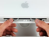
Use your thumbs to press both RAM arms in past the front bezel for enough clearance to lift it off the rear case.
-
-
-
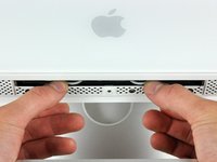
While holding the RAM arms in with your thumbs, lift the lower edge of the front bezel enough to clear the rear case.
-
-
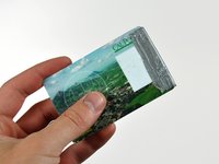
Инструмент, используемый на этом этапе:Plastic Cards$2.99
-
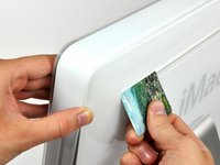
Insert a plastic card up into the corner of the air vent slot near the top of the rear case.
-
Push the card toward the top of the iMac to release the front bezel latch.
-
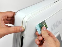
Pull the front bezel away from the rear case.
-
Repeat this process for the other side of the front bezel.
-
If the bezel refuses to release, try pressing the lower edge back onto the rear case and repeat this opening process.
-
-
-
Lay your iMac stand-side down on a table.
-
Lift the front bezel from its lower edge and rotate it away from the rest of your iMac, minding the RAM arms that may get caught.
-
Lay the front bezel above the rest of the iMac.
-
-
-
If necessary, remove the piece of kapton tape wrapped around the microphone and camera connectors.
-
-
-
Peel the lower EMI shield off the lower edge of the iMac and off the two vertical 4" sections on either side of the iMac.
-
-
-
Tape the lower EMI shield up against the face of the display to keep it out of the way while you work.
-
-
-
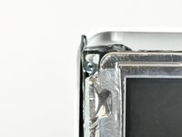
Remove the two T6 Torx screws securing the display data cable connector to the logic board.
-
-
-
To disconnect the display data cable, grab its connector's black tab and pull it away from the face of the logic board.
-
-
-
Peel back the two EMI tape strips from the left and right edges of the display.
-
-
-
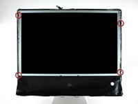
Remove the four recessed T10 Torx screws securing the display to the rear case.
-
-
-
Lift the lower edge of the display slightly out of the rear case.
-
Disconnect both inverter cables (shown in red) by pulling their connectors toward the bottom edge of your iMac.
-
-
-
Lift the display until it is nearly perpendicular to the rear case.
-
Disconnect the remaining two inverter cables (shown in red) by pulling their connectors toward the top edge of your iMac.
-
-
-
While holding the display perpendicular to the rear case, pull it upward to peel off the EMI shield stuck to its upper edge.
-
-
-
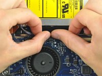
Disconnect the IR board cable by pulling its connector away from the socket on the IR board.
-
-
-
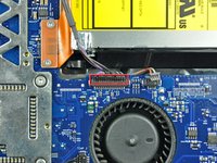
De-route the IR cable from under the aluminum heat sink and tuck it behind the optical drive to keep it out of the way.
-
-
-
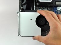
Remove the single T10 Torx screw securing the left speaker to the rear case.
-
Lift the left speaker out of the rear case and de-route its cable across the logic board.
-
-
-
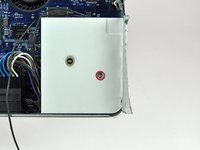
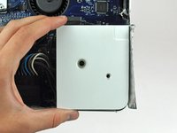
Remove the single T10 Torx screw securing the right speaker to the rear case.
-
Lift the right speaker out of the rear case, minding the short cable between the speaker and its connector (located slightly above the right speaker).
-
-
-
Disconnect the speakers from the logic board by pulling their connector toward the top edge of the iMac.
-
-
-
Remove the two Phillips or two T6 Torx screws securing the AirPort/Bluetooth board to the logic board.
-
-
-
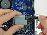
Use your finger to lift the AirPort/Bluetooth board from its left edge, disconnecting it from the logic board.
-
-
-
Use the flat end of a spudger to pry both antenna cable connectors up off the AirPort/Bluetooth board.
-
-
-
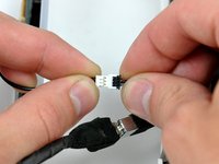
Disconnect the DC-in cable by simultaneously depressing both locking arms and pulling its connector away from the socket on the logic board toward the top of your iMac.
-
-
-
Disconnect the ambient light sensor by pulling its connector away from the face of the logic board.
-
-
-
Disconnect the optical drive thermal sensor cable from the logic board by pulling its connector toward the left edge of the iMac.
-
-
-
Remove the two T6 Torx screws securing the optical drive connector to the logic board.
-
-
-
Use the flat end of a spudger to pry the optical drive connector up off the logic board.
-
-
-
Disconnect the CPU fan from the logic board by pulling its connector toward the top edge of the iMac.
-
-
-
Disconnect the hard drive thermal sensor from the logic board by pulling its connector toward the top edge of the iMac.
-
-
-
Disconnect the hard drive fan by pulling its connector away from the face of the logic board.
-
-
-
Disconnect the power button cable by pulling its connector away from the face of the logic board.
-
-
-
Remove the following seven screws securing the logic board to the rear case:
-
Three coarse-thread T10 Torx.
-
Three fine-thread T10 Torx.
-
One long coarse-thread T10 Torx.
-
-
-
Tuck the RAM arms into the iMac so they rest on the perforated metal grille along its lower edge.
-
-
-
Rotate the top of the logic board toward yourself slightly.
-
Pull the right edge of the logic board toward yourself slightly to free the I/O ports from the rear case, being careful not to bend the board.
-
Continue rotating the board toward yourself until you have enough room to reach the SATA connector, shown in the next step.
-
-
-
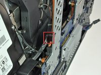
Continue rotating the board toward yourself until you have enough room to reach the SATA connector (shown in red).
-
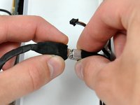
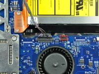
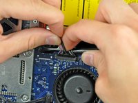
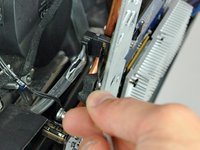
Insert the blunt end of a metal spudger between the SATA connector and its socket. Twist the shaft of the metal spudger to separate the connector from its socket.
-
Disconnect the SATA cable from the logic board.
-
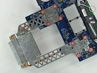
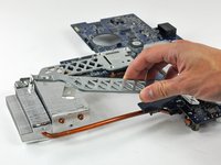
Lift the logic board out of the rear case by its edges, minding any cables that may get caught.
-
-
-
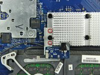
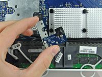
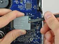
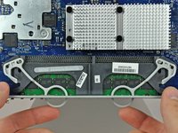
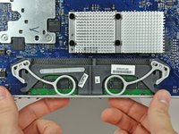
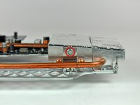
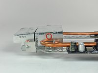
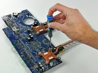
Remove the 6.1 mm T8 Torx screw from both sides of the heat sink nearest the logic board (two screws total).
-
-
-
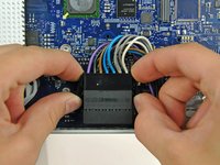
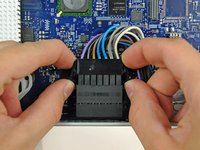
Remove the following ten screws:
-
Eight 7.8 mm T8 Torx.
-
Two 6.1 mm T8 Torx.
-
If the eight screws around the processors refuse to unscrew, use a Phillips screwdriver to hold the lug from the one side of the board while you remove the Torx screw from the other side.
-


To reassemble your device, follow these instructions in reverse order.
To reassemble your device, follow these instructions in reverse order.
Отменить: Я не выполнил это руководство.
Еще один человек закончил это руководство.
