Этот документ имеет более свежие изменения. Перейти к последней непроверенной версии.
Введение
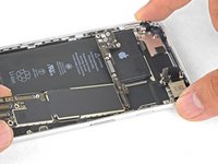
Follow this guide to remove and replace the logic board for the iPhone 8.
Note: Each iPhone's logic board and Touch ID fingerprint sensor are paired at the factory, so replacing the logic board will disable Touch ID unless you also install a replacement home button that has been properly paired to your new logic board.
Выберете то, что вам нужно
-
-
-
Remove the two 3.5 mm pentalobe screws on the bottom edge of the iPhone.
 Спросите у FixBot
-
-
-
-
-
Measure 3 mm from the tip and mark the opening pick with a permanent marker.
-
-
-
-
Инструмент, используемый на этом этапе:Clampy - Anti-Clamp$24.95
-
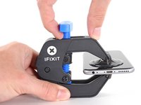
Pull the blue handle backwards to unlock the Anti-Clamp's arms.
-
Slide the arms over either the left or right edge of your iPhone.
-
Position the suction cups near the bottom edge of the iPhone just above the home button—one on the front, and one on the back.
-
Squeeze the cups together to apply suction to the desired area.
-
-
-
Pull the blue handle forwards to lock the arms.
-
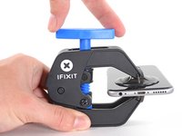
Turn the handle clockwise 360 degrees or until the cups start to stretch.
-
Make sure the suction cups remain aligned with each other. If they begin to slip out of alignment, loosen the suction cups slightly and realign the arms.
-
-
-
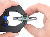
Heat an iOpener and thread it through the arms of the Anti-Clamp.
-
Fold the iOpener so it lays on the bottom edge of the iPhone.
-
Wait one minute to give the adhesive a chance to release and present an opening gap.
-
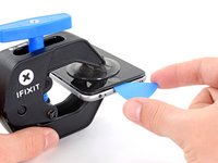
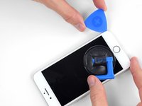
Insert an opening pick into the gap.
-
Skip the next three steps.
-
-
-
Heating the lower edge of the iPhone will help soften the adhesive securing the display, making it easier to open.
-
Use a hairdryer or prepare an iOpener and apply it to the lower edge of the phone for about 90 seconds in order to soften up the adhesive underneath.
-
-
-
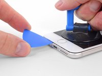
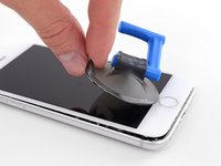
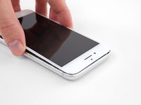
Apply a suction cup to the lower half of the front panel, just above the home button.
-
-
-
Pull up on the suction cup with firm, constant pressure to create a slight gap between the screen and the frame.
-
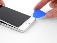
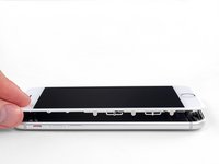
Insert an opening pick into the gap.
-
-
-
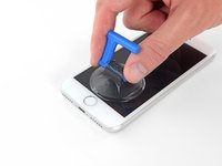
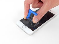
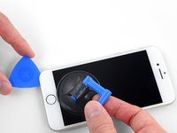
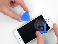
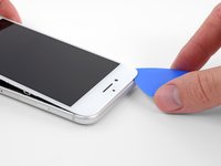
Slide the opening pick up the left edge of the phone starting at the lower edge and moving towards the volume control buttons and silent switch, breaking up the adhesive holding the display in place.
-
Stop near the top left corner of the display.
-
-
-
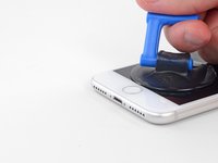
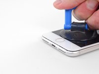
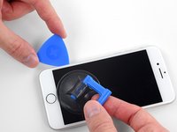
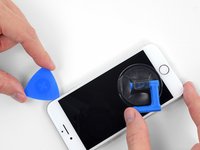
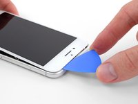
Re-insert your tool at the lower right corner of the iPhone, and slide it around the corner and up the right side of the phone to separate the adhesive.
-
-
-
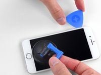
Gently pull up on the suction cup to lift up the bottom edge of the display.
-
Pull on the small nub on the suction cup to remove it from the front panel.
-
-
-
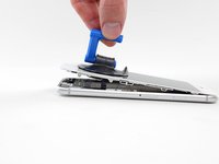
Slide an opening pick underneath the display around the top left corner and along the top edge of the phone to loosen the last of the adhesive.
-
-
-
Slide the display assembly slightly down (away from the top edge of the phone) to disengage the clips holding it to the rear case.
-
-
-
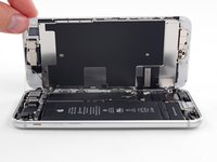
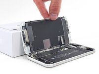
Open the iPhone by swinging the display up from the left side, like the back cover of a book.
-
Lean the display against something to keep it propped up while you're working on the phone.
-
-
-
-
-
Инструмент, используемый на этом этапе:Magnetic Project Mat$19.95
-
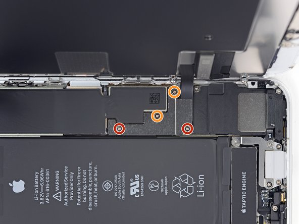
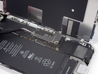
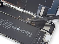
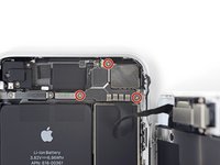
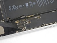
Remove four Phillips screws securing the lower display cable bracket to the logic board, of the following lengths:
-
Two 1.3 mm screws
-
Two 2.8 mm screws
-
Remove the bracket.
-
-
-
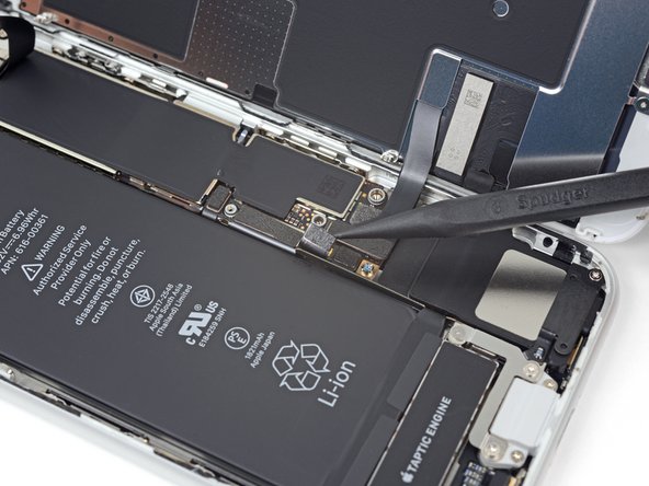
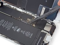
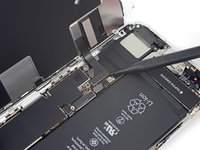
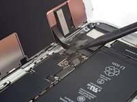
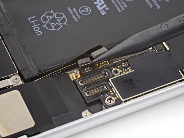
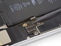
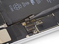
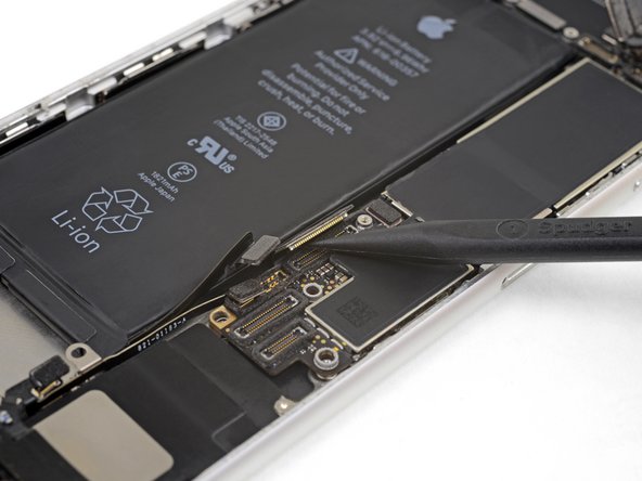
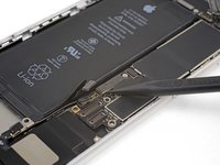
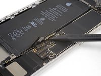
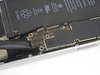
Use the point of a spudger to pry the battery connector out of its socket in the logic board.
-
Bend the battery connector cable slightly away from the logic board to prevent it from accidentally making contact with the socket and providing power to the phone during your repair.
-
-
-
-
-
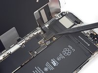
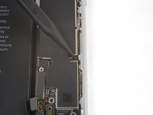
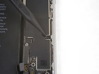
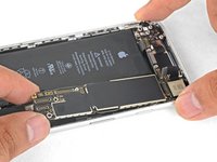
Use the point of a spudger to pry the lower display connector out of its socket.
-
-
-
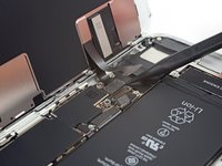
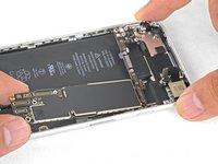
Use the point of a spudger to disconnect the second lower display cable.
-
-
-
Remove the three 1.3 mm Phillips screws securing the bracket over the front panel sensor assembly connector.
-
Remove the bracket.
-
-
-
Use the point of a spudger to disconnect the front panel sensor assembly connector.
-
-
-
-
-
Insert a SIM card eject tool, bit, or a straightened paperclip into the small hole in the SIM card tray.
-
Press to eject the tray.
-
-
-
-
-
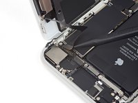
Use the flat end of a spudger to disconnect the camera cable connector by prying it straight up from its socket.
-
-
Инструмент, используемый на этом этапе:Standoff Screwdriver for iPhones$5.49
-
Remove the two screws securing the rear-facing camera bracket:
-
One 3.0 mm standoff screw
-
One 3.1 mm Phillips screw
-
-
-
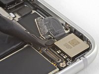
Use the point of a spudger to disconnect the flash connector from its socket by prying it straight up.
-
-
-
Remove the two screws securing the upper cable bracket:
-
One 2.9 mm Phillips screw
-
One 1.3 mm Phillips screw
-
-
-
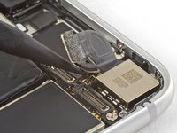
Use the flat end of a spudger to pry the upper cable connector up from its socket.
-
-
-
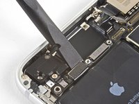
Remove the three Phillips 1.3 mm screws securing the top left antenna component.
-
-
-
Remove the 1.4 mm Phillips screw securing the antenna component to the top of edge of the case.
-
-
-
Remove the two Phillips screws securing the grounding clip at the top left edge of the logic board:
-
One 1.5 mm Phillips screw
-
One 2.6 mm Phillips screw
-
-
-
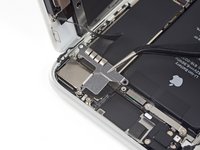
Remove the three screws securing the motherboard:
-
One 1.8 mm Phillips screw
-
One 2.5 mm standoff screw
-
One 2.2 mm standoff screw
-
-
Инструмент, используемый на этом этапе:Tweezers$4.99
-
Use tweezers to gently bend the logic board grounding bracket out of the way.
-
-
-
Use the point of a spudger to move the SIM card eject plunger out of the logic board's way.
-
-
-
-
-
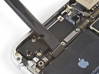
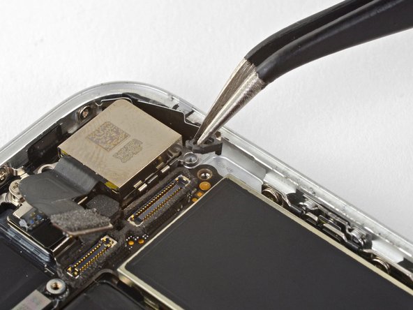
Use the point of a spudger to pry up and disconnect the Wi-Fi diversity antenna cable.
-
-
-
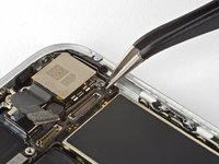
Use the point of a spudger to pry up and disconnect the Lightning cable connector.
-
-
-
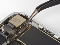
Use the point of a spudger to pry up and disconnect the wireless charging coil connector.
-
-
-
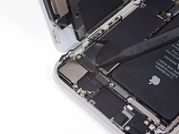
Use the flat end of a spudger to gently lift the battery connector end of the logic board up.
-
-
-
Grasping it by the edges, lift the logic board near the battery connector and remove it.
-
-


To reassemble your device, follow the above steps in reverse order.
Take your e-waste to an R2 or e-Stewards certified recycler.
Repair didn’t go as planned? Check out our Answers community for troubleshooting help.
Отменить: Я не выполнил это руководство.
98 человек успешно провели ремонт по этому руководству.


20 Комментарии к руководству
Hello evryone. Do I need a new touch ID that fits the motherboard or can I use my old touch ID?
The motherboards that are for sale, sell with touch ID and without. That`s why I am asking.
Hi Sebastian,
Yes, the Touch ID is paired with the motherboard. In order to keep Touch ID functionality, you have to use the fingerprint sensor that comes with the replacement.
can i use this process two switch a logic board from a working i phone to one that is icloud locked?
That’s why I’m here
Hi Kenneth,
The phone’s “identity” is based off of the logic board, so switching a logic board will remove the iCloud lock—if the replacement logic board is not locked. Note that the Touch ID hardware is paired each logic board.