Введение
Use this guide to replace the upper case, which includes the keyboard. This procedure involves using adhesive remover to remove the battery. Do not reuse the battery after it has been removed, as doing so is a potential safety hazard. Replace it with a new battery.
iFixit adhesive remover is highly flammable. Perform this procedure in a well-ventilated area. Do not smoke or work near an open flame during this procedure.
To minimize risk of damage, turn on your MacBook and allow the battery to fully discharge before starting this procedure. A charged lithium-ion battery can create a dangerous and uncontrollable fire if accidentally punctured. If your battery is swollen, take extra precautions.
Some replacement upper case assemblies may include the trackpad and battery as well. In this case, skip steps 18 through 44.
This guide requires the removal of the heat sink. Don't forget to follow our thermal paste application guide before you reinstall your heat sink.
Выберете то, что вам нужно
-
Инструмент, используемый на этом этапе:Magnetic Project Mat$19.95
-
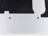
Remove the following ten screws securing the lower case to the upper case:
-
Two 2.3 mm P5 Pentalobe screws
-
Eight 3.0 mm P5 Pentalobe screws
-
-
-
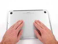
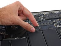
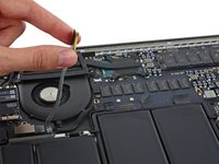
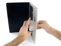
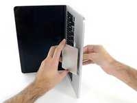
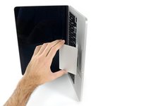
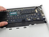
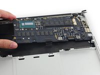
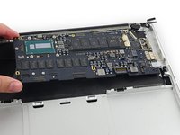
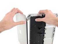
Wedge your fingers between the upper case and the lower case.
-
Gently pull the lower case away from the upper case to remove it.
-
-
-
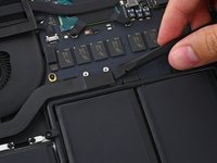
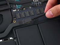
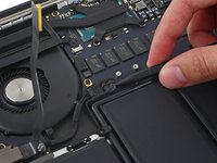
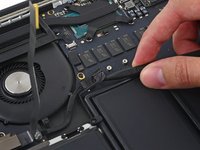
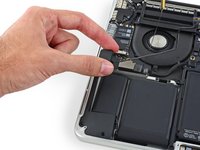
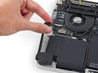
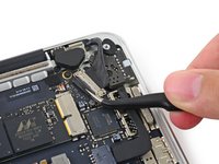
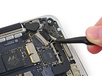
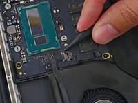
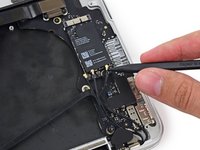
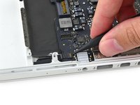
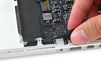
Use the flat end of a spudger to lift the battery connector straight up out of its socket on the logic board.
-
-
-
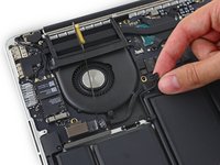
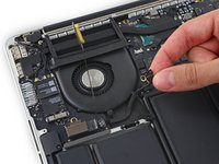
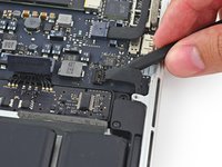
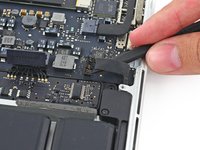
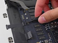
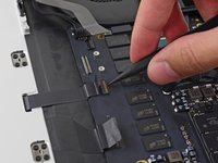
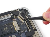
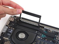
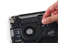
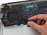
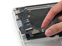
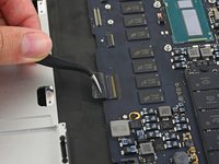
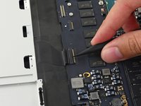
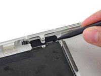
Remove the two 2.1 mm T5 Torx screws securing the logic board end of the I/O board cable bracket.
-
-
Инструмент, используемый на этом этапе:Tweezers$4.99
-
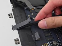
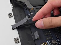
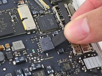
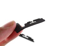
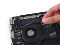
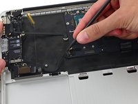
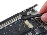
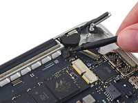
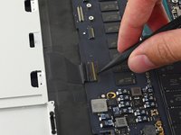
Grasp the I/O board cable bracket with a pair of tweezers and remove it from the MacBook.
-
-
-
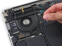
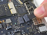
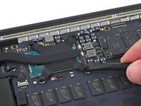
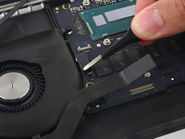
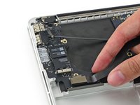
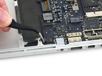
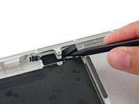
Use the flat end of a spudger to pop the I/O board connector straight up off its socket on the logic board.
-
-
-
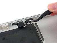
Lift the logic board end of the I/O board cable straight up to bend it out of the way.
-
-
-
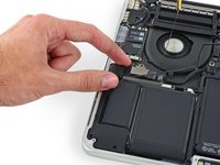
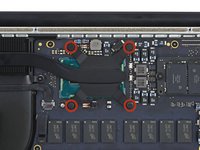
Carefully tuck the tip of a spudger under the right speaker cable near the connector and lift it up out of its socket on the logic board.
-
-
-
Remove the following screws securing the right speaker to the upper case:
-
One 5.7 mm T5 Torx screw
-
One 6.5 mm T5 Torx screw
-
One 3.8 mm T5 Torx screw
-
-
-
Insert the tip of a spudger under the left speaker cable near the connector and lift it up out of its socket on the logic board.
-
-
-
Remove the following screws securing the left speaker to the upper case:
-
One 5.7 mm T5 Torx screw
-
One 6.5 mm T5 Torx screw
-
One 3.8 mm T5 Torx screw
-
-
-
Lift the corner of the left speaker up and slide it out around the battery to remove it from the upper case.
-
-
-
Heat the iOpener for thirty seconds.
-
Throughout the repair procedure, as the iOpener cools, reheat it in the microwave for an additional thirty seconds at a time.
-
-
-
Remove the iOpener from the microwave, holding it by one of the two flat ends to avoid the hot center.
-
-
-
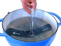
Fill a pot or pan with enough water to fully submerge an iOpener.
-
Heat the water to a boil. Turn off the heat.
-
Place an iOpener into the hot water for 2-3 minutes. Make sure the iOpener is fully submerged in the water.
-
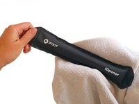
Use tongs to extract the heated iOpener from the hot water.
-
Thoroughly dry the iOpener with a towel.
-
Your iOpener is ready for use! If you need to reheat the iOpener, heat the water to a boil, turn off the heat, and place the iOpener in the water for 2-3 minutes.
-
-
-
Remove the five 3.7 mm T5 Torx screws securing the battery to the upper case.
-
-
-
To protect your display, place a sheet of aluminum foil between the display and keyboard and leave it there while you work.
-
-
-
Alternatively, if you are using the hot iOpener method, skip the following three steps.
-
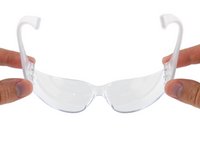
Wear eye protection when handling and applying the adhesive remover. (Eye protection is included in your kit.)
-
Do not wear contact lenses without eye protection.
-
Protective gloves are also included in your kit. If you are concerned about skin irritation, put your gloves on now.
-
-
-
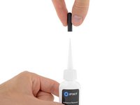
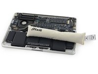
Pull off the black rubber stopper from your bottle of adhesive remover.
-
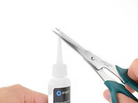
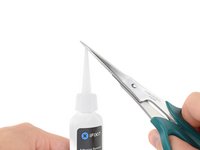
Use scissors to cut off the sealed tip of the applicator.
-
-
-
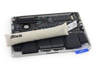
Apply a few drops of adhesive remover evenly under the edge of the rightmost battery cell.
-
Wait 2-3 minutes for the liquid adhesive remover to penetrate underneath the battery cell before you proceed to the next step.
-
-
-
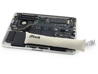
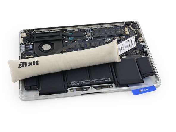
Use the hot iOpener to cover half of the two right-most battery cells.
-
After about a minute, reheat the iOpener and move it to cover the other half of the right-most battery cells.
-
-
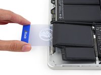
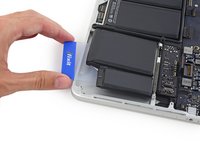
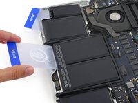
Инструмент, используемый на этом этапе:Plastic Cards$2.99
-
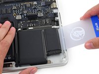
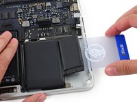
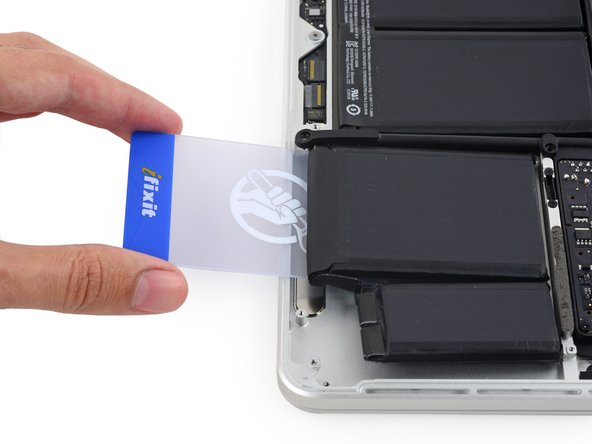
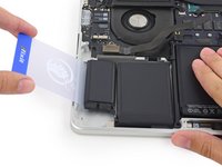
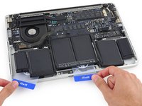
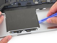
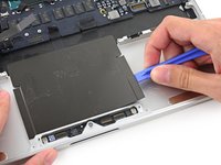
Push a plastic card between the right-most battery cell and the upper case, cutting the adhesive between the two.
-
When using the hot iOpener method, if you encounter significant resistance to prying, stop and use the iOpener to reheat the section you're working on.
-
-
-
-
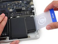
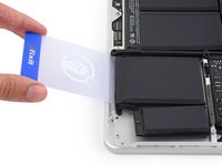
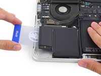
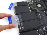
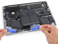
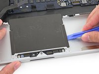
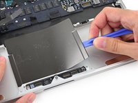
Repeat this procedure with the adjacent battery cell:
-
Apply a small amount of liquid adhesive remover under the battery cell, and wait 2-3 minutes for it to penetrate and soften the adhesive.
-
Alternatively, re-heat this section with your iOpener if needed.
-
Push a plastic card about an inch between the battery cell and the upper case, and slowly pry the cell up to separate all of the adhesive.
-
-
-
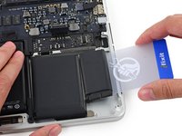
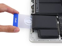
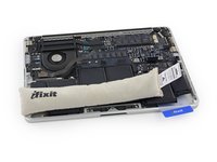
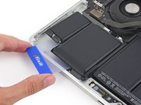
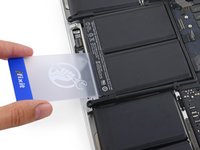
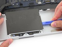
Temporarily leave your plastic card underneath the two rightmost battery cells to prevent them from re-adhering to the upper case.
-
If using an iOpener, reheat it and reapply it, this time to the left-most battery cells.
-
-
-
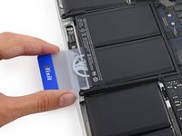
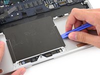
Repeat the above procedure to separate the two leftmost battery cells from the upper case.
-
Remember to apply a small amount of adhesive remover to each battery cell, and wait 2-3 minutes for it to penetrate and soften the adhesive.
-
Use a second plastic card to separate the two leftmost battery cells from the upper case.
-
-
-
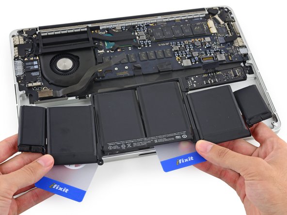
To separate the adhesive securing the final two, middle battery cells, apply a few more drops of liquid adhesive remover (or your iOpener) to each cell.
-
It may help to elevate one side of your MacBook Pro a few inches so that the adhesive remover flows in the correct direction, underneath the battery cells. You can use a sturdy book or foam block to prop up one side of your MacBook Pro while you work.
-
Insert the card about an inch between the left-center battery cell and the upper case, separating the adhesive between the cell and the case.
-
-
-
Pull the card back out and insert it about an inch between the right-center battery cell and the upper case, separating the adhesive between the cell and case.
-
-
-
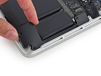
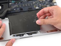
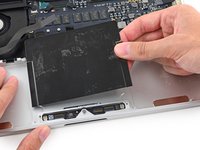
Pry up on the two center cells to separate the last of the adhesive and lift the battery from the device.
-
-
-
Remove the battery.
-
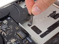
With a little luck, you can slowly pull out each strip of adhesive with your fingers.
-
Otherwise, soak each section of adhesive with a bit of adhesive remover for 2-3 minutes, and then scrape it out with an opening pick or one of the other tools in your kit. This can take quite a bit of work, so be patient.
-
Mop up any remaining adhesive remover and give your MacBook Pro a few minutes to air dry.
-
Calibrate your newly installed battery: charge it to 100%, and keep charging it for at least 2 more hours. Unplug and use it normally to drain the battery. When you see the low battery warning, save your work, and keep your laptop on until it goes to sleep due to low battery. Wait at least 5 hours, then charge your laptop uninterrupted to 100%.
-
-
-
Place a reheated iOpener over the trackpad cover plate to soften the adhesive securing it to the upper case.
-
-
-
Use a plastic opening tool to carefully pry the trackpad cover plate up from the upper case.
-
-
-
Use a plastic opening tool to slowly and carefully peel the trackpad cover plate up off the upper case.
-
-
-
Wedge the flat end of a spudger underneath the upper case opening where the trackpad ribbon cable passes is routed through.
-
Gently pry the trackpad ribbon cable from the adhesive securing it to the upper case.
-
-
-
Remove the following screws securing the trackpad brackets to the trackpad and upper case.
-
Four 2.2 mm T5 Torx screws
-
Four 1.7 mm T5 Torx screws
-
-
Инструмент, используемый на этом этапе:Tweezers$4.99
-
Use tweezers to remove the two trackpad mounting brackets from the upper case.
-
-
-
Carefully guide the trackpad ribbon cable through the slot cut in the upper case.
-
Guide the trackpad out of the upper casewith your other hand, so it doesn't fall.
-
-
-
Gently pull the trackpad away from the upper case, being careful not to snag the ribbon cable.
-
-
-
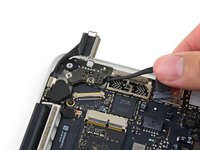
Grab the black plastic tab to flip the display cable connector open and pull it straight out of its socket on the logic board.
-
Pull in the direction of the cable, parallel to the logic board. Do not pull up.
-
-
-
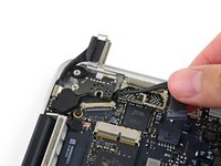
Remove the two 3.5 mm T5 Torx screws securing the MagSafe DC-In board to the upper case.
-
-
-
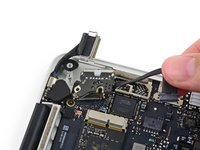
Use the MagSafe DC-In board cable to pull the board out and up from the upper case to remove it.
-
-
-
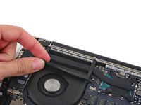
Carefully remove the rubber fan bumper from the edge of the heat sink.
-
-
-
Use the flat end of a spudger to peel the four foam stickers off of the heat sink screws.
-
-
-
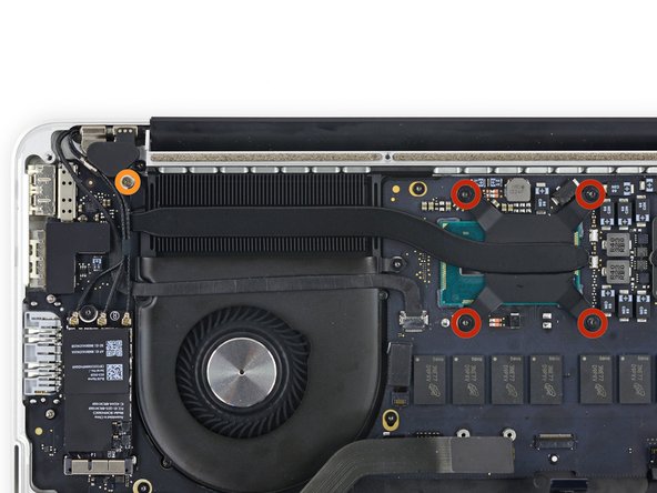
Remove the following screws securing the heat sink:
-
Four 2.6 mm T5 screws
-
One 2.4 mm Phillips #000 screw
-
-
-
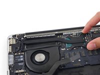
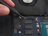
Use the tip of a spudger to push on either side of the the iSight camera cable connector and walk it out of its socket on the logic board.
-
-
-
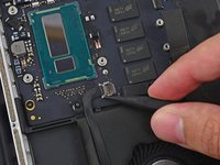
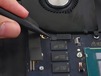
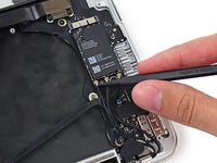
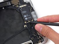
Use the tip of a spudger to flip the tab on the fan's ZIF connector.
-
Carefully pull the fan cable from its connector.
-
-
-
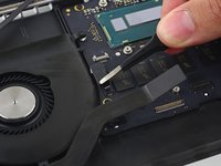
Remove the following screws securing the fan to the upper case:
-
One 5.0 mm T5 Torx screw
-
Two 3.6 mm T5 Torx screws
-
-
-
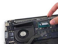
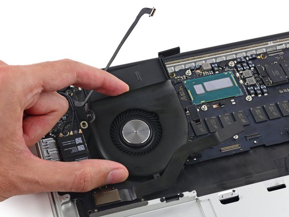
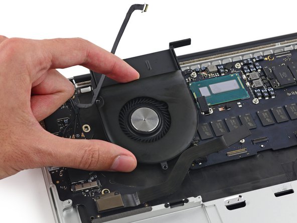
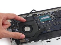
Lift the end of the fan from the heat sink cavity and pull it up and out toward the hinge of the laptop to remove it.
-
-
-
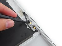
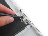
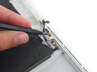
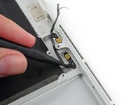
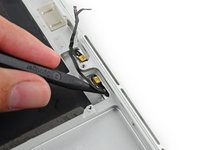
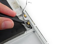
Insert the tip of a spudger under each of the antenna cables near their connectors and pry up to disconnect them from the AirPort board.
-
Connect the long-sleeved cable to the center socket.
-
The short-sleeved cable connects next to the screw.
-
The remaining cable has no sleeve, and connects in the last empty socket, next to the fan.
-
-
-
With the tip of a spudger, push on either side of the I/O board connector to walk it out of its socket on the logic board.
-
-
-
Remove the following screws securing the I/O board to the upper case:
-
One 3.5 mm T8 Torx standoff screw
-
One 3.5 mm T5 Torx screw
-
-
-
Lift the I/O board cable end of the I/O board and pull toward the logic board to free the ports from the upper case.
-
Remove the I/O board.
-
-
-
Use the flat end of a spudger to disconnect the keyboard backlight cable and move it out of the way.
-
-
-
Use the tip of a spudger to flip the retaining tab on the microphone cable ZIF connector.
-
-
-
Remove the five 3.5 mm T5 Torx screws securing the logic board to the upper case.
-
-
-
Lift the processor end of the logic board up slightly and pull it toward the fan recess to free the ports from the edge of the upper case and remove the logic board.
-
-
Инструмент, используемый на этом этапе:Tweezers$4.99
-
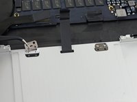
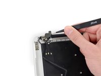
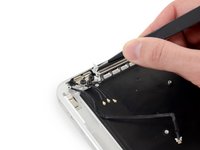
Use a pair of tweezers to lift the rubber hinge covers up off the right and left display hinges.
-
-
-
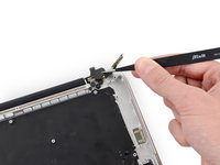
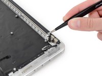
Remove the 3.2 mm T5 Torx screws (one on each side) securing the aluminum hinge brackets to the upper case.
-
-
-
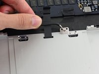
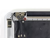
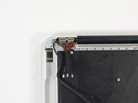
Use a pair of tweezers to lift aluminum hinge brackets off the right and left display hinges.
-
-
-
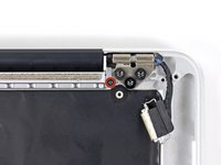
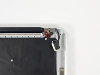
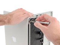
Remove the four inner 5.3 mm T8 Torx screws (two on each side) securing the display to the upper case.
-
-
-
While holding the display and upper case together with your left hand, remove the remaining T8 Torx screw from the lower display bracket.
-
Remove the last remaining T8 Torx screw securing the display to the upper case.
-
-
-
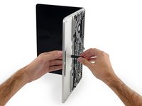
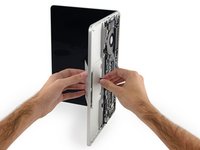
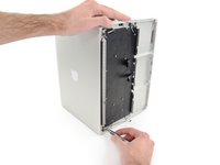
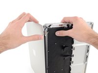
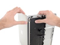
Grip both halves of the device, one in each hand.
-
Gently push forward on the bottom half of the device to detach it from the display assembly.
-
Carefully set each component aside, making sure to set down the lower half keyboard-side down.
-
-
-
Place the MacBook on a heated iOpener for about a minute to soften the adhesive securing the dual microphone cable.
-
-
-
Insert the tip of a spudger under the rubber microphone cable cover to free it form the upper case.
-
Remove the rubber microphone cable cover.
-
-
-
Insert the tip of a spudger under the connector end of the microphone ribbon cable and lift to peel that section up from the upper case.
-
-
-
Insert the tip of a spudger under the right-hand portion of the microphone ribbon cable and slide it toward the screw post to free it from the upper case.
-


To reassemble your device, follow these instructions in reverse order.
To reassemble your device, follow these instructions in reverse order.
Отменить: Я не выполнил это руководство.
21 человек успешно провели ремонт по этому руководству.


7 Комментариев
hey there! steps seem very useful, really hope that this will work. but what am i going to do after the replacement? now i “only“ know how to get to the upper case. is there any instruction for putting the mac book back together after replacing the upper case? would be thankful for that advice!
I have just done this repair now and it all went great with the help of this article. I purchased a second hand top case which had a battery, trackpad, keyboard, speakers and microphones still in tact and in good condition. This allows you to skip nearly 50% of the steps in this tutorial. Highly recommended to try and find something similar yourself. Slow and steady is definitely the way to do this repair and if you do that and use the right tools you will find the repair to be easy and painless. Best of luck to all.
Took a tad over 2 hours to do, including the screen. Have to remember to reset the SMC controller (Once repaired press Control, option, power button for 10 sec after shut down. Then hit power button again). I watched the cpu temp with Fanny to make sure the new thermal paste was applied correctly and used rubbing alcohol to do the cleaning.
Kudos on a great guide. Did what Mr. Davies did, saves a lot of heartache. Battery removals are not enjoyable one bit. Looked for a top case sub $60 with a low battery cycle count (250 and below),
Managed to get this done in about 2.5 hours, but I was able to skip some steps. Goal was replacing upper case assembly to get a working keyboard. I managed to replace the logic board without removing the heatsink, which was the only step I really wanted to avoid due to manual application of thermal paste as opposed to the dot method. I also managed to find an upper case replacement with only about 100 cycles on it and a working trackpad, so not having to replace the batteries or trackpad saved time and effort as well. Need to check temps just in case— and still need to test the I/O ports to be sure. But overall, great guide- very comprehensive. Just use the sections you need. FYI - if you’re planning on replacing the keyboard for this machine, plan on replacing the whole Upper Case Assembly. My understanding from others giving advice are that keys are riveted on and very difficult to replace. You’re better off swapping out the whole upper case.
Hi
I purchased by mistake a 2015 upper case for my 2014 Macbook Pro (both A1502)
Having dismantled the MBP I noticed that the trackpad is different therefore I ordered the proper model and ribbon cable
Will this installed (2015) upper case be compatible with my MBP 2014 ?
thanks
yann