
iPhone 8 Plus Wi-Fi Diversity Antenna Flex

Введение
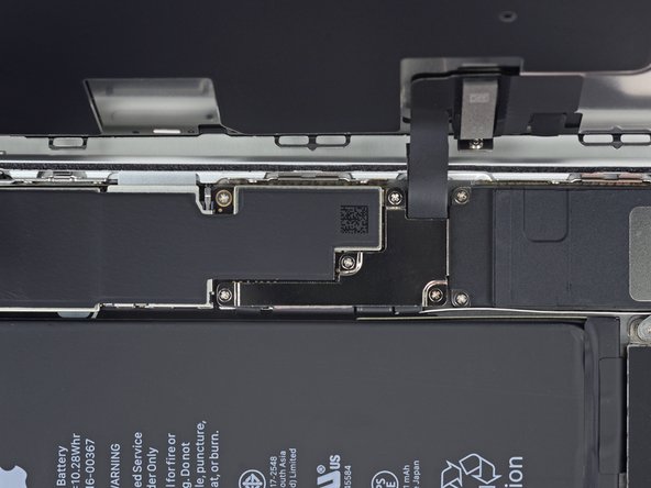
Перейти к шагу 1Use this guide to replace the small flex cable running from the Lightning connector flex to the logic board in the iPhone 8 Plus. Replacing it may resolve a number of connectivity issues.
Выберете то, что вам нужно
Запчасти


Инструменты


Показать больше…
-
-
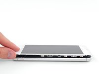
Power off your iPhone before beginning disassembly.
-
Remove the two 3.5 mm pentalobe screws from the bottom edge of the iPhone.
-
-
-
Measure 3 mm from the tip and mark the opening pick with a permanent marker.
-
-
-
Lay overlapping strips of clear packing tape over the iPhone's screen until the whole face is covered.
-
If you can't get the suction cup to stick in the next few steps, fold a strong piece of tape (such as duct tape) into a handle and lift the screen with that instead.
-
-
Инструмент, используемый на этом этапе:Clampy - Anti-Clamp$24.95
-
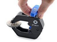
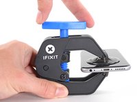
Pull the blue handle backwards to unlock the Anti-Clamp's arms.
-
Slide the arms over either the left or right edge of your iPhone.
-
Position the suction cups near the bottom edge of the iPhone just above the home button—one on the front, and one on the back.
-
Squeeze the cups together to apply suction to the desired area.
-
-
-
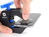
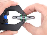
Pull the blue handle forwards to lock the arms.
-
Turn the handle clockwise 360 degrees or until the cups start to stretch.
-
Make sure the suction cups remain aligned with each other. If they begin to slip out of alignment, loosen the suction cups slightly and realign the arms.
-
-
-
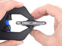
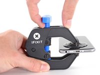
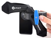
Heat an iOpener and thread it through the arms of the Anti-Clamp.
-
Fold the iOpener so it lays on the bottom edge of the iPhone.
-
Wait one minute to give the adhesive a chance to release and present an opening gap.
-
Insert an opening pick under the screen when the Anti-Clamp creates a large enough gap.
-
Skip the next three steps.
-
-
-
Use a hairdryer or prepare an iOpener and apply it to the lower edge of the iPhone for about 90 seconds in order to soften up the adhesive underneath.
-
-
-
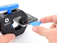
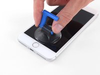
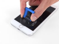
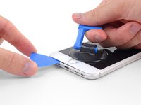
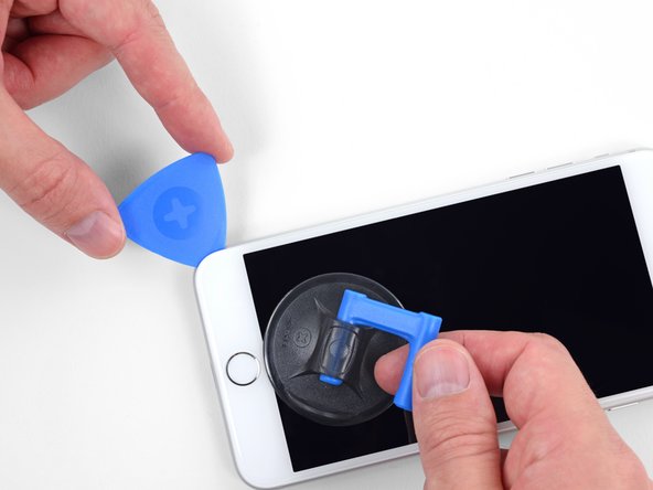
Apply a suction cup to the lower half of the front panel, just above the home button.
-
-
-
Pull up on the suction cup with firm, constant pressure to create a slight gap between the front panel and rear case.
-
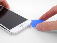
Insert an opening pick or other thin pry tool a few millimeters into the gap.
-
-
-
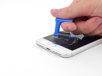
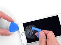
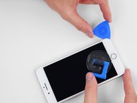
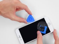
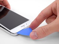
Slide your pick around the corner and up the left edge of the phone, moving towards the volume control buttons and silent switch, breaking up the adhesive holding the display in place.
-
Stop near the top left corner of the display.
-
-
-
-
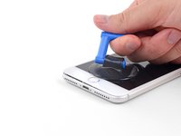
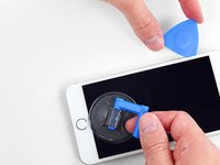
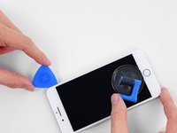
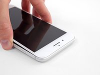
Re-insert your tool at the lower right corner of the iPhone, and slide it around the corner and up the right side of the phone to separate the adhesive.
-
-
-
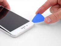
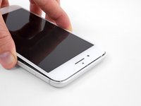
Slide an opening pick underneath the display along the top edge of the phone to loosen the last of the adhesive.
-
-
-
Slide the display assembly slightly down (away from the top edge of the phone) to disengage the clips holding it to the rear case.
-
-
-
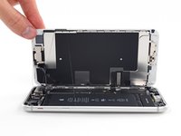
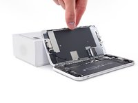
Open the iPhone by swinging the display up from the left side, like the back cover of a book.
-
Lean the display against something to keep it propped up while you're working on the phone.
-
-
Инструмент, используемый на этом этапе:Magnetic Project Mat$19.95
-
Remove four Phillips (JIS) screws securing the lower display cable bracket to the logic board, of the following lengths:
-
Two 1.3 mm screws
-
One 1.4 mm screw
-
One 2.7 mm screw
-
-
-
Use the point of a spudger to pry the battery connector up from its socket on the logic board.
-
Bend the connector cable up slightly to prevent it from accidentally making contact with the socket and providing power to the phone during your repair.
-
-
-
Use the tip of a spudger or a fingernail to disconnect the large lower display connector by prying it straight up from its socket.
-
-
-
Disconnect the second lower display cable connector, directly behind the one you disconnected in the previous step.
-
-
-
Remove the two tri-point Y000 screws securing the bracket over the front panel sensor assembly connector:
-
One 1.0 mm screw
-
One 1.2 mm screw
-
-
-
Use the tip of a spudger or a fingernail to disconnect the front panel sensor assembly connector from its socket.
-
-
-
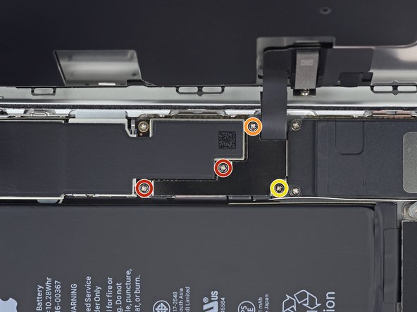
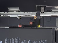
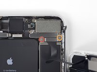
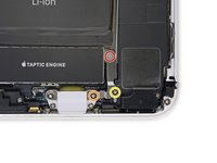
Remove the three screws securing the L-shaped bracket next to the Taptic Engine:
-
One 1.3 mm Y000 screw
-
One 2.6 mm Phillips screw
-
One 3.5 mm Phillips screw
-
-
-
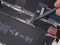
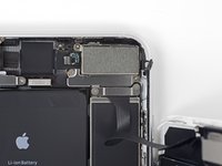
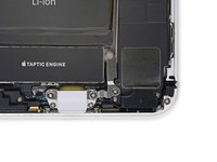
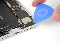
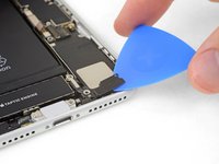
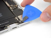
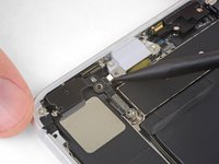
Use an opening pick to gently separate the adhered portion of the antenna flex cable from the top surface of the speaker.
-
-
-
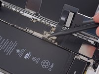
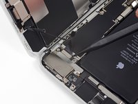
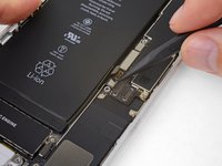
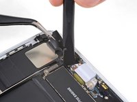
Use the point of a spudger to pry up and disconnect the antenna flex cable from the logic board.
-
-
Инструмент, используемый на этом этапе:Tweezers$4.99
-
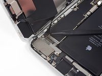
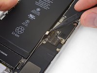
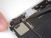
Use the point of your spudger to pry up and disconnect the other end of the antenna flex cable from its socket, next to the Lightning Port.
-


Compare your new replacement part to the original part—you may need to transfer remaining components or remove adhesive backings from the new part before installing.
To reassemble your device, follow the above steps in reverse order.
Take your e-waste to an R2 or e-Stewards certified recycler.
Repair didn’t go as planned? Check out our Answers community for troubleshooting help.
Отменить: Я не выполнил это руководство.
18 человек успешно провели ремонт по этому руководству.


4 Комментариев
My Cellular data connection keeps connecting and disconnecting consistently. I received a message “Could not activate cellular data network”'.
WiFi and Bluetooth work fine. Could this possibly fix my issue or is it more of motherboard issue?
Thank you if anyone can help. My phone is out of warranty
Same problem. Any solutions? Thank you.
So I broke the plug in on the logic board where you plug in for WiFi, is that fixable . Oh I broke the plug in for the LED light also
This is cellular antenna btw.