Введение
Use this guide to remove or replace the front shell (front cover) on a Steam Deck LCD.
Remember: follow general electrostatic discharge (ESD) safety procedures while repairing your device.
This procedure involves almost a complete disassembly, including removing the display! Know what you're getting yourself into. You'll need replacement adhesives for the display and speakers.
Выберете то, что вам нужно
-
-
Power down your Steam Deck and unplug any cables.
 Спросите у FixBot
-
-
Инструмент, используемый на этом этапе:FixMat$36.95
-
Use a Phillips driver to remove the eight screws securing the back cover:
-
Four coarse thread 9.5 mm-long screws
-
Four fine thread 5.8 mm-long screws
-
-
-
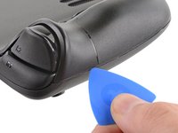
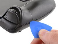
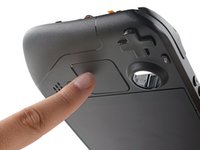
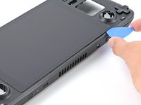
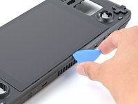
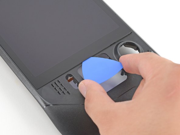
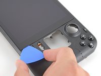
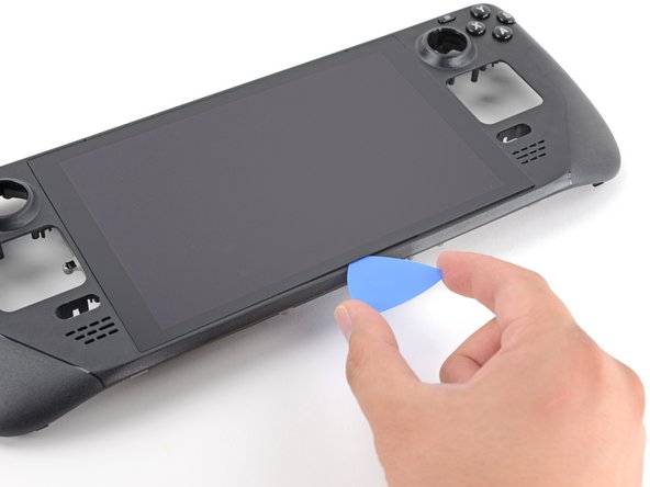
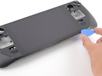
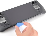
Insert an opening pick into the thin gap between the back cover and the front shell, along the edge of the right grip.
-
Pry up on the back cover to release it from the locking clips.
-
-
-
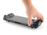
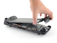
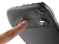
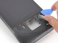
Grip the back cover at the opening you just created and pull it up and away from the device to unclip the long edges.
-
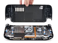
Remove the back cover.
-
-
Инструмент, используемый на этом этапе:Tweezers$4.99
-
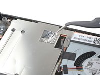
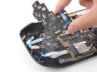
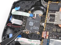
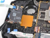
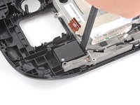
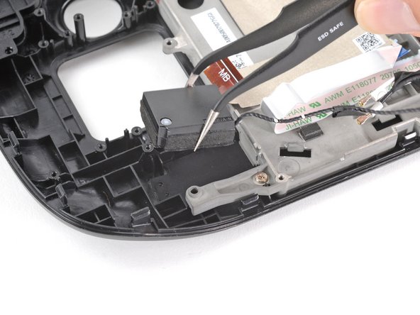
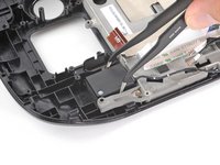
Use a pair of tweezers to remove the piece of foil tape covering the hidden screw on the board shield.
-
-
-
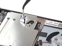
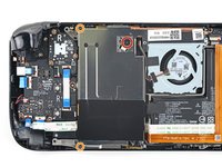
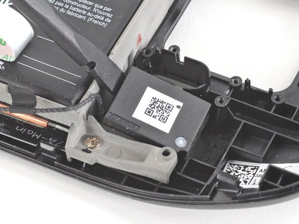
Use a Phillips driver to remove the three screws securing the board shield:
-
One 3.4 mm screw
-
Two 3.7 mm screws
-
-
-
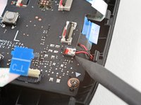
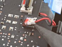
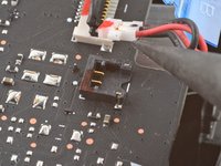
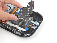
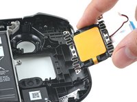
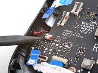
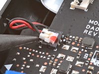
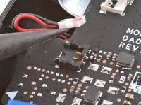
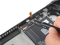
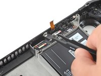
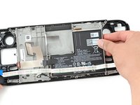
Grip the battery cable by its pull tab and pull it directly away from the motherboard to disconnect it.
-
-
-
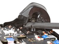
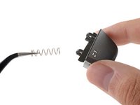
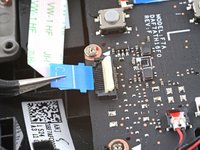
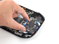
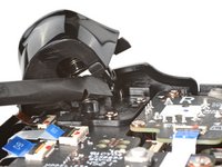
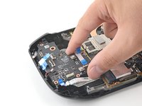
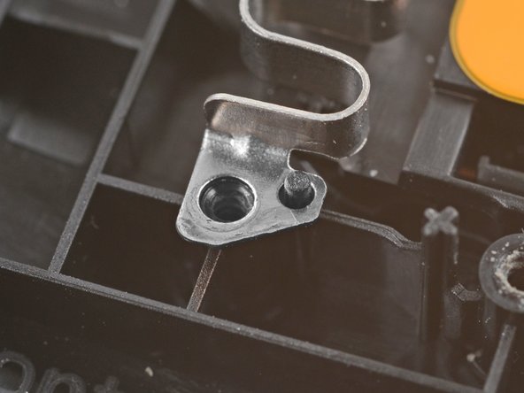
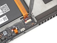
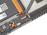
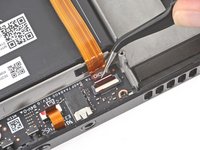
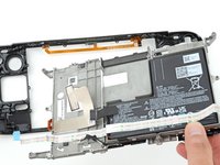
Place the flat end of a spudger onto the inside edge of the trigger's left clip.
-
Pivot the trigger clip out, away, and up from the peg to unlatch it.
-
-
-
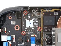
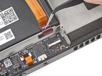
Use a Phillips driver to remove the three 5.2 mm screws securing the left trigger bracket.
-
-
Инструмент, используемый на этом этапе:Tweezers$4.99
-
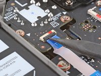
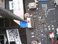
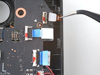
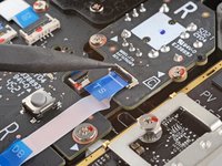
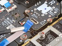
Use the pointed end of a spudger to lift up the small locking flap on the thumbstick cable's ZIF connector.
-
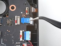
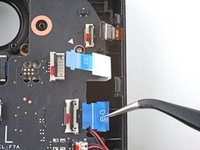
Use a pair of tweezers to slide the cable out of its connector.
-
-
-
Use a Phillips driver to remove the three 5.2 mm screws securing the thumbstick.
-
-
-
Use the pointed end of a spudger to lift up the small locking flap on the button board interconnect cable's ZIF connector.
-
Use a pair of tweezers to slide the cable out of its connector.
-
-
-
If any connectors are covered with tape, use a pair of tweezers to remove it.
-
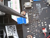
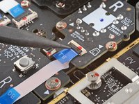
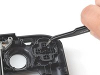
Use the pointed end of a spudger to lift up the small locking flaps on the rest of the button board ZIF connectors. Use a pair of tweezers to slide the cables out of their connectors:
-
Disconnect the D-pad cable.
-
Disconnect the touchpad board cable.
-
Disconnect the touchpad cable.
-
-
-
Use the pointed end of a spudger to lift up on the haptics cable to disconnect it.
-
-
-
Use a Phillips driver to disconnect the four screws securing the left button board:
-
Three 5.2 mm screws
-
One 3.9 mm screw
-
-
-
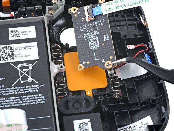
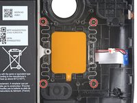
Use a Phillips driver to remove the four 4.7 mm screws securing the touchpad board.
-
-
-
Use a Phillips driver to remove the four 4.7 mm screws securing the touchpad.
-
-
-
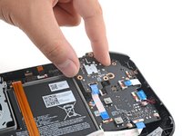
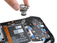
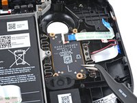
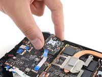
From the front of the Steam Deck, use your finger to push the left touchpad partway through the front shell to unseat it.
-
Lift the touchpad out from underneath the overhanging section of the midframe.
-
Remove the touchpad.
-
-
-
Place the flat end of a spudger onto the inside edge of the trigger's right clip.
-
Pivot the trigger clip out, away, and up from the peg to unlatch it.
-
-
-
Use a Phillips driver to remove the three 5.2 mm screws securing the right trigger bracket.
-
-
Инструмент, используемый на этом этапе:Tweezers$4.99
-
Use the pointed end of a spudger to lift up the small locking flap on the thumbstick cable's ZIF connector.
-
Use a pair of tweezers to slide the cable out of its connector.
-
-
-
Use a Phillips driver to remove the three 5.2 mm screws securing the thumbstick.
-
-
-
Use the pointed end of a spudger to lift up the small locking flap on the button board cable's ZIF connector.
-
Use a pair of tweezers to slide the cable out of its connector.
-
-
-
Use the pointed end of a spudger to lift up the small locking flap on the button board interconnect cable's ZIF connector.
-
Use a pair of tweezers to slide the cable out of its connector.
-
-
-
If any connectors are covered with tape, use a pair of tweezers to remove it.
-
Use the pointed end of a spudger to lift up the small locking flaps on the rest of the button board ZIF connectors. Use a pair of tweezers to slide the cables out of their connectors:
-
Disconnect the action buttons cable.
-
Disconnect the touchpad board cable.
-
Disconnect the touchpad cable.
-
-
-
Use the pointed end of a spudger to lift up on the haptics cable to disconnect it.
-
-
-
-
Use a Phillips driver to disconnect the four screws securing the right button board:
-
Three 5.2 mm screws
-
One 3.9 mm screw
-
-
-
Use a Phillips driver to remove the four 4.7 mm screws securing the touchpad board.
-
-
-
Use a Phillips driver to remove the four 4.7 mm screws securing the touchpad.
-
-
-
From the front of the Steam Deck, use your finger to push the right touchpad partway through the front shell to unseat it.
-
Lift the touchpad out from underneath the overhanging section of the midframe.
-
Remove the touchpad.
-
-
Инструмент, используемый на этом этапе:Tweezers$4.99
-
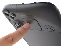
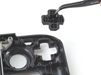
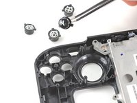
Use a pair of tweezers to remove the quick access button membrane.
-
-
-
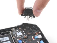
Use a pair of tweezers to remove the quick access button.
-
-
-
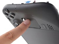
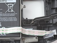
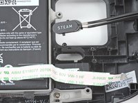
Use a pair of tweezers to remove the Steam button membrane.
-
-
-
Use a pair of tweezers to remove the Steam button.
-
-
-
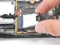
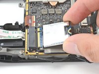
Use a Phillips driver to remove the 3.4 mm screw securing the SSD.
-
-
-
Grip the end of the SSD and pull it away from its M.2 board connector to remove it.
-
-
-
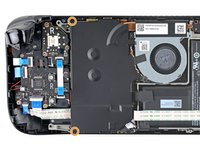
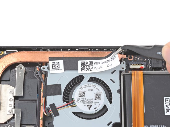
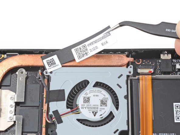
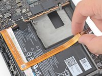
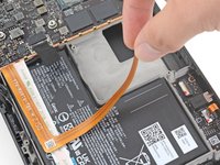
Use a pair of tweezers to remove the sticker from the top edge of the fan.
-
-
-
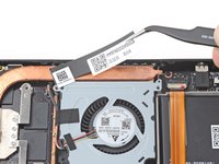
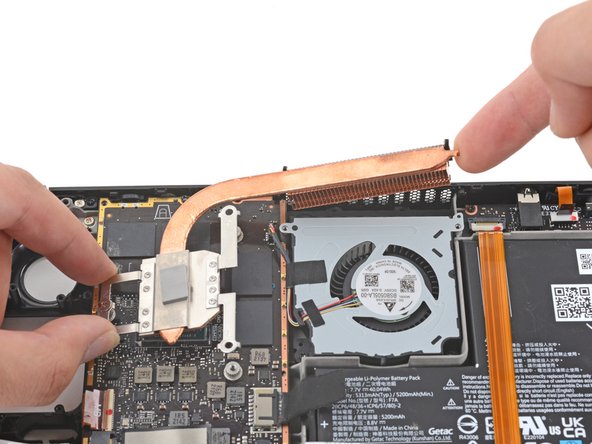
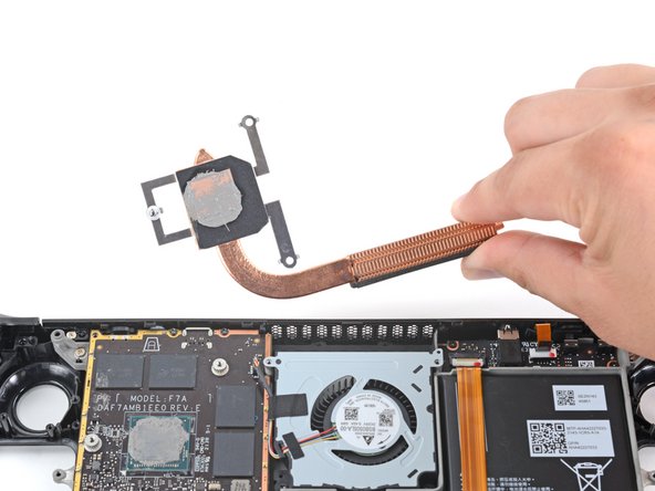
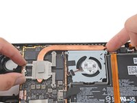
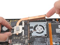
Use a Phillips driver to loosen and remove the two screws securing the heatsink to the motherboard:
-
One captive 3.5 mm screw
-
One 3.4 mm screw
-
-
-
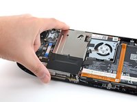
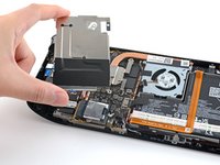
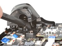
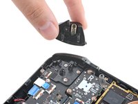
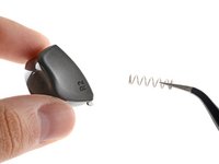
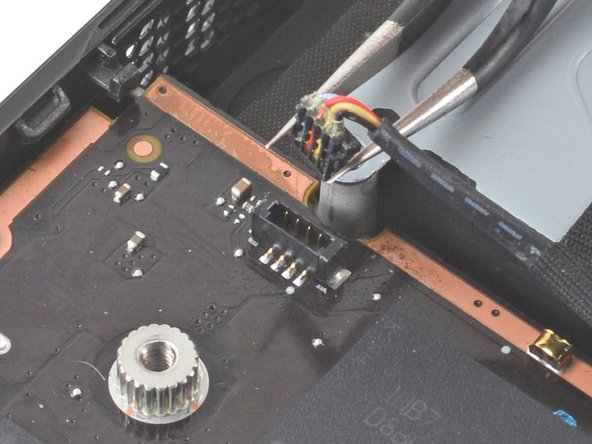
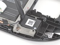
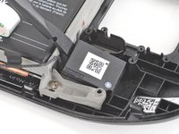
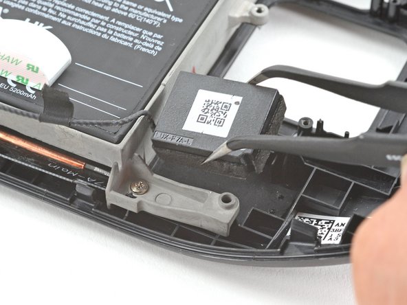
Use a pair of tweezers to grip the edges of the fan connector and pull up to disconnect it from the motherboard.
-
-
-
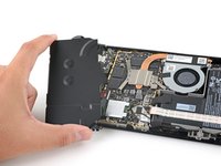
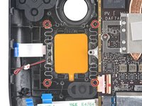
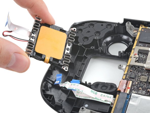
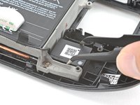
Use a Phillips driver to remove the two 3.7 mm screws securing the fan.
-
-
-
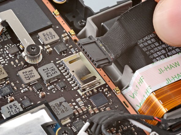
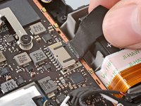
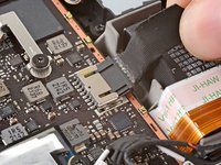
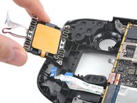
Use a pair of tweezers to grip the edges of the speaker connector and pull up to disconnect it from the motherboard.
-
-
-
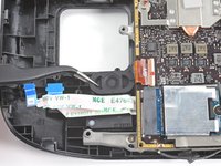
Use a pair of tweezers to peel up and remove the Wi-Fi shield tape.
-
-
-
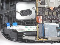
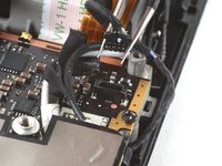
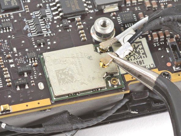
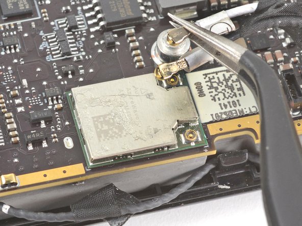
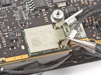
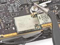
Use a pair of tweezers to grip the antenna connector close to its base.
-
Pull straight up to disconnect the cable.
-
Repeat for the second antenna cable.
-
-
-
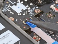
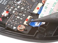
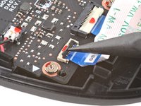
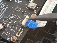
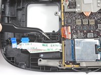
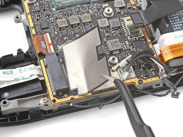
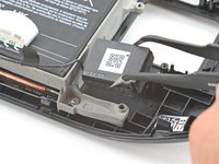
Use the pointed end of a spudger to lift up the small locking flap on the display cable's ZIF connector.
-
Use a pair of tweezers to slide the cable out of its connector.
-
-
-
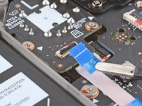
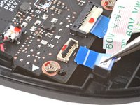
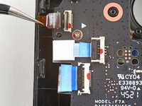
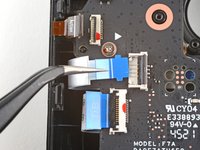
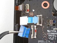
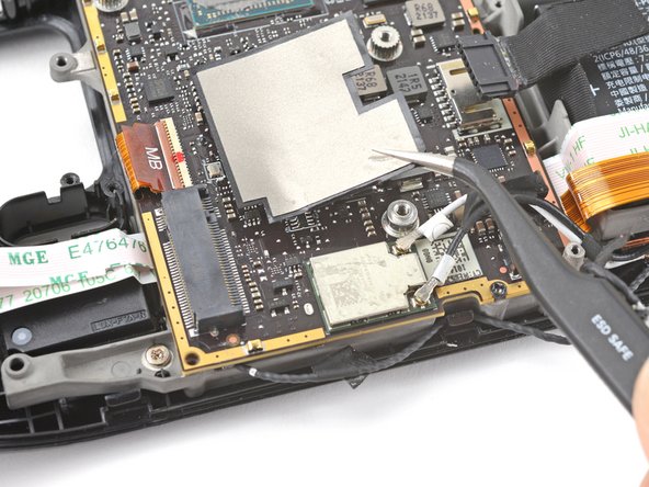
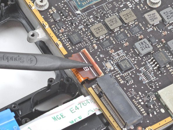
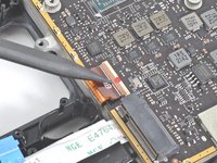
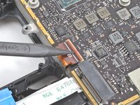
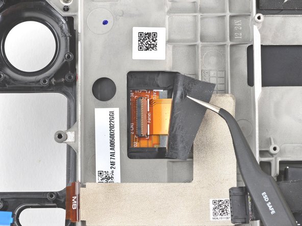
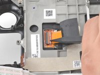
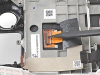
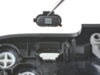
Use the pointed end of a spudger to lift up the small locking flap on the audio cable's ZIF connector.
-
-
-
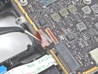
Use a pair of tweezers to slide the cable out of its connector.
-
-
-
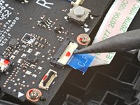
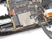
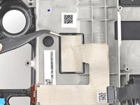
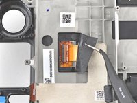
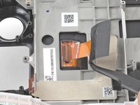
Carefully peel the audio cable off of the battery.
-
If the adhesive is stubborn, don't force the cable. Lightly heat the audio cable using an iOpener or a hair dryer to soften the adhesive.
-
-
-
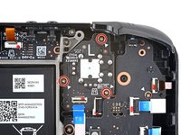
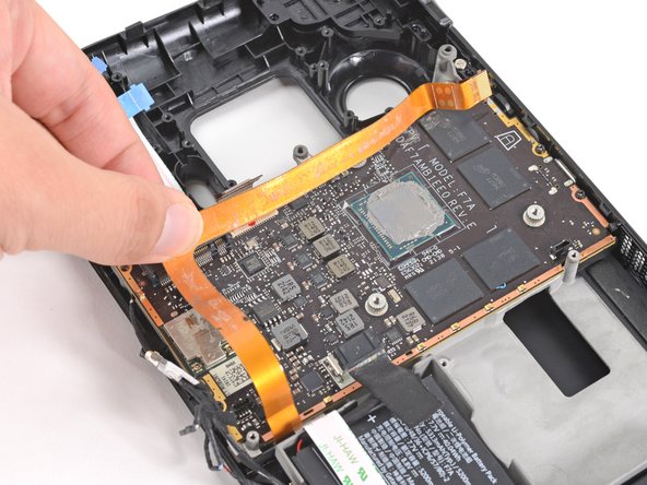
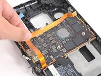
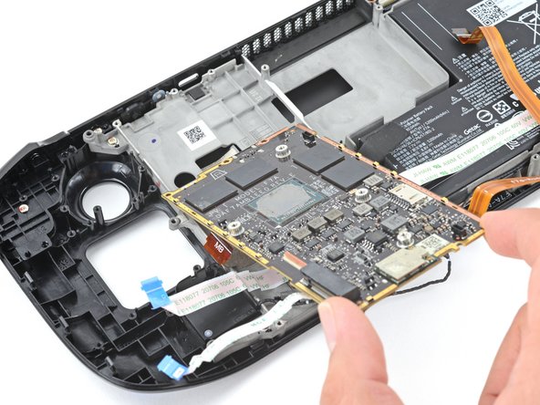
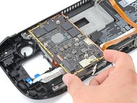
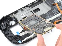
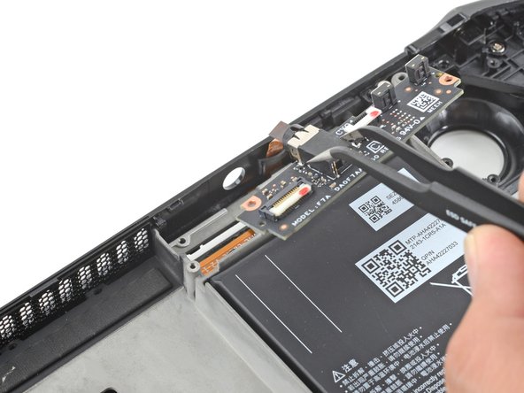
Use a Phillips driver to remove the three 3.7 mm screws securing the motherboard.
-
-
-
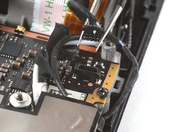
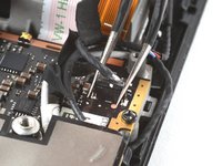
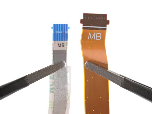
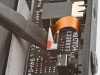
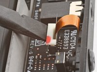
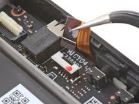
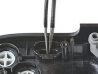
Use the pointed end of a spudger to lift up on the mic cable's white locking tab.
-
Use a pair of tweezers to pull the mic cable up and out of its connector.
-
-
-
Use a Phillips driver to remove the two 3.7 mm screws securing the audio board.
-
-
-
Use a pair of tweezers to grip the audio board by the headphone jack.
-
Pivot the board up and out of its recess to remove it.
-
-
-
Use a pair of tweezers to peel up the tape bundling the speaker wire to the Wi-Fi antenna cables.
-
-
-
Use a pair of tweezers to peel up the various strips of black tape routing the speaker wire along the bottom edge of the chassis.
-
-
-
Insert the flat end of a spudger between the right speaker and the frame.
-
Pivot the spudger up to separate the speaker from the light adhesive securing it against the front shell.
-
-
-
Use a pair of tweezers to grip and remove the right speaker from its cavity.
-
-
-
Insert the flat end of a spudger between the left speaker and the frame.
-
Pivot the spudger up to separate the speaker from the light adhesive securing it against the front shell.
-
-
-
Use a pair of tweezers to grip and remove the left speaker from its cavity.
-
-
-
Remove the tethered right and left speakers.
-
-
-
Use a pair of tweezers to peel back the sticker covering the display connector.
-
-
-
Use the pointed end of a spudger to lift up the small locking flap on the display cable's ZIF connector.
-
Use a pair of tweezers to slide the cable out of its connector.
-
-
-
Prepare an iOpener and apply it to the top edge of the display for one minute.
-
-
-
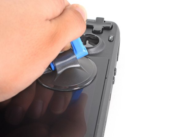
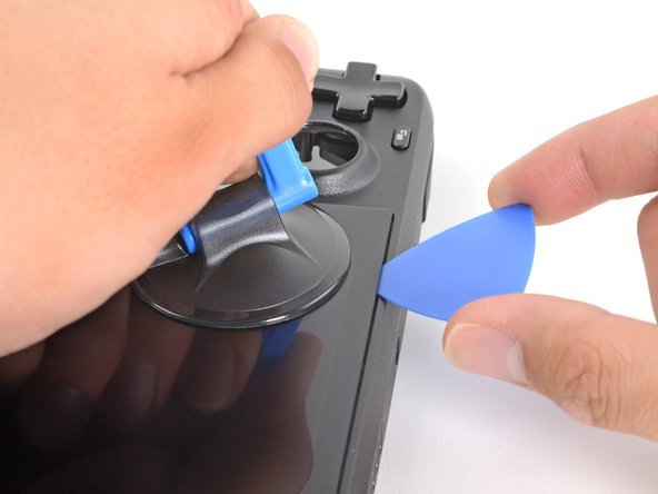
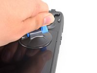
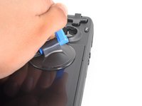
Apply a suction cup to the top left corner of the display by pressing down on it to create suction, as close to the edge as possible.
-
Pull up on the suction cup with strong, steady force to create a gap between the display and the frame.
-
Insert the point of an opening pick into the gap.
-
-
-
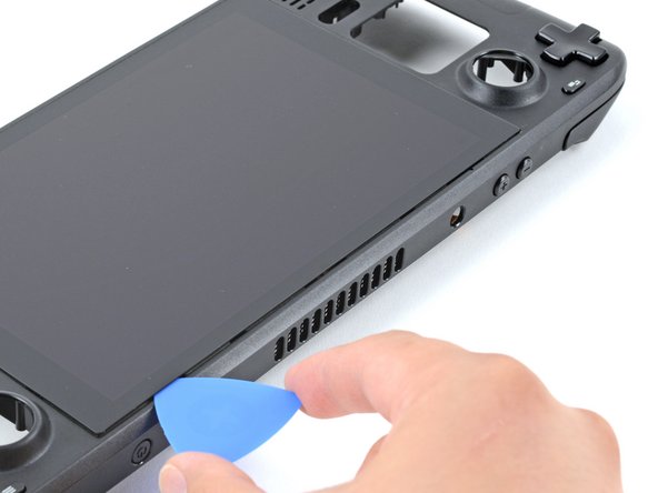
Slide the opening pick no more than 3 mm deep across the top edge to slice the adhesive.
-
-
-
Heat the right edge of the display for one minute.
-
-
-
Slide the opening pick down the right edge to slice the adhesive.
-
-
-
Heat the bottom edge of the display for one minute.
-
-
-
Slide the opening pick across the bottom edge to slice the adhesive.
-
-
-
Heat the left edge of the display for one minute.
-
Slide the opening pick across the left edge to slice the adhesive.
-
-
-
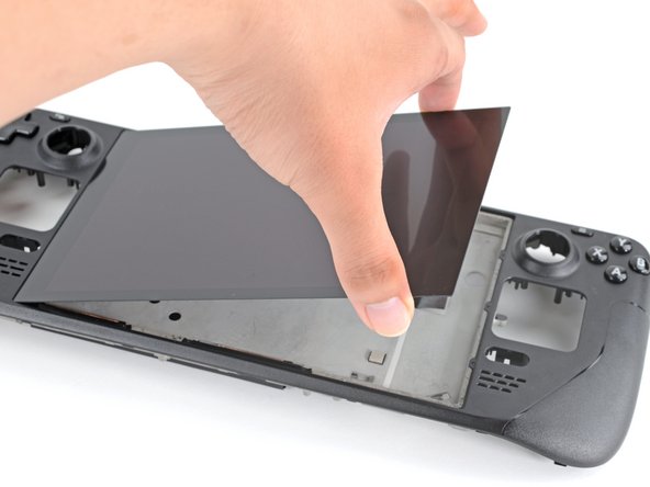
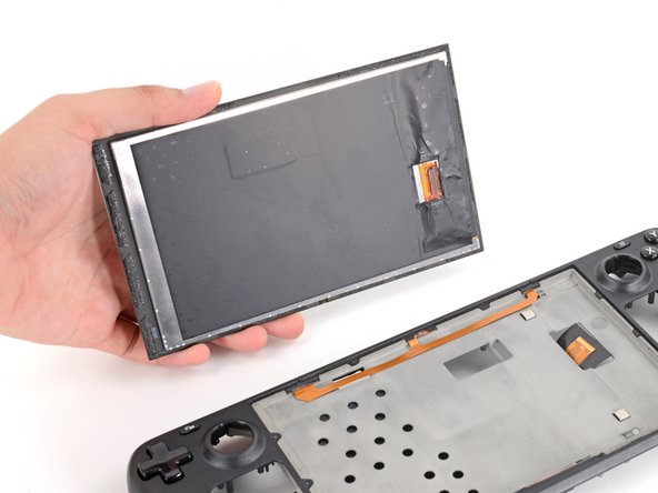
Once you have sliced around the perimeter of the display, carefully lift the right edge up, opening it like a book.
-
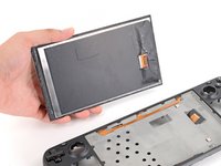
Remove the display.
-
-
-
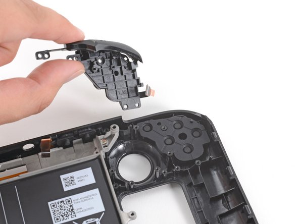
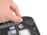
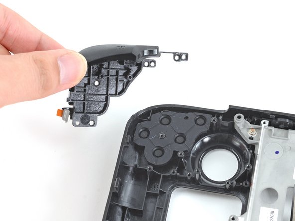
Use a Phillips driver to remove the two 5.2 mm screws securing the left bumper assembly.
-
-
-
Remove the left bumper assembly.
-
-
-
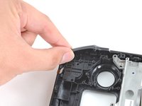
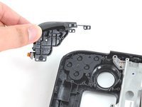
Use a Phillips driver to remove the two 5.2 mm screws securing the right bumper assembly.
-
-
-
Remove the right bumper assembly.
-
-
-
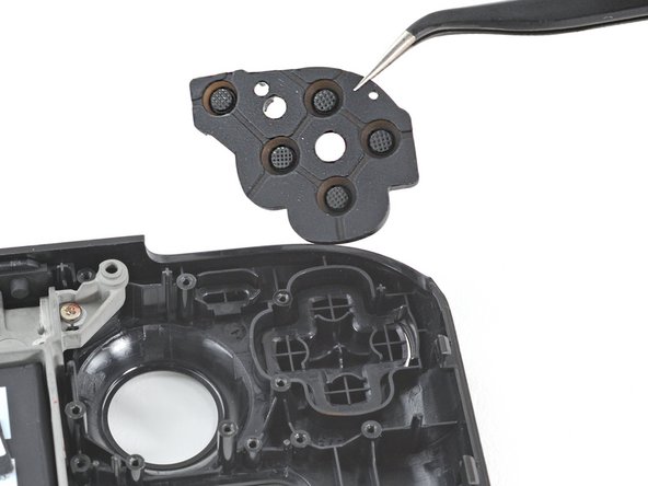
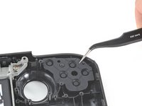
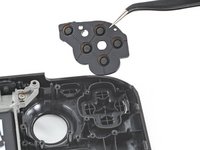
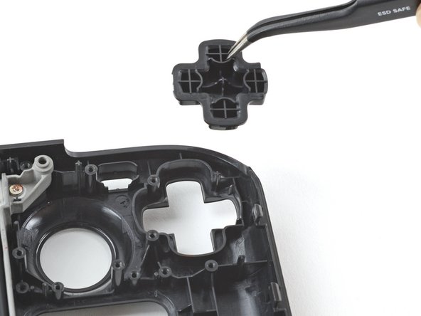
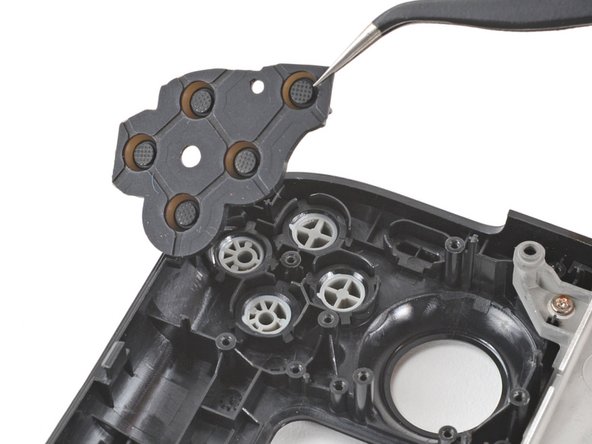
Use a pair of tweezers to remove the D-pad membrane.
-
-
-
Use a pair of tweezers to remove the action buttons membrane.
-
-
-
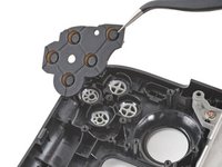
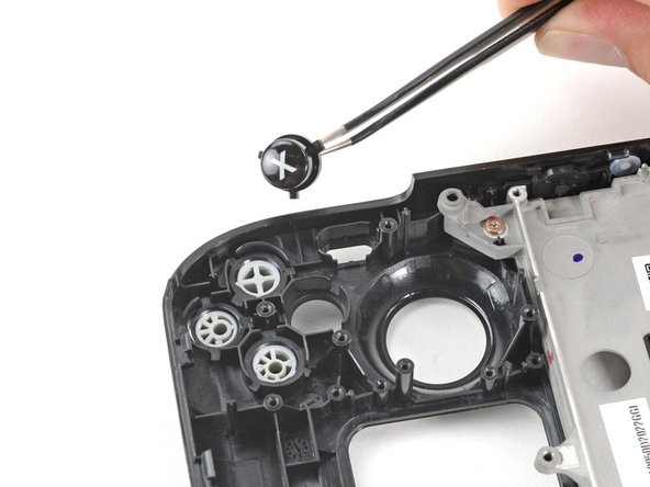
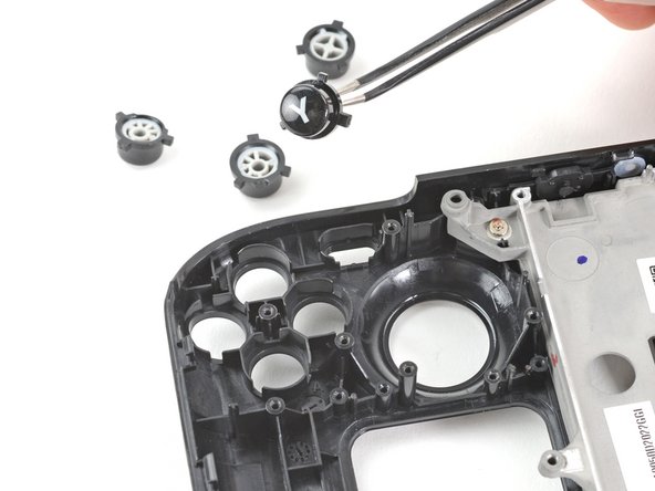
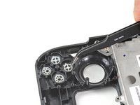
Use a pair of tweezers to remove the four action buttons, A, B, X, and Y.
-
-
-
Use a pair of tweezers to remove the view button.
-
-
-
Use a pair of tweezers to remove the menu button.
-
-
-
Use a Phillips driver to remove the six 2.3 mm screws securing the midframe to the front shell, located on the front side.
-
-
-
Use a Phillips driver to remove the four 5.2 mm screws securing the midframe to the front shell.
-
-
-
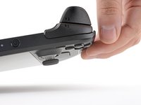
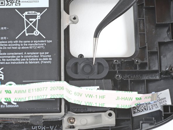
Use the pointed end of a spudger to lift the rubber flap to the left of the volume buttons up and out of its plastic clip.
-
-
-
Use a pair of tweezers to remove the volume buttons by pulling them up and away from the front shell.
-
-
-
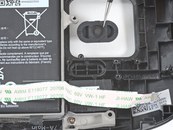
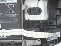
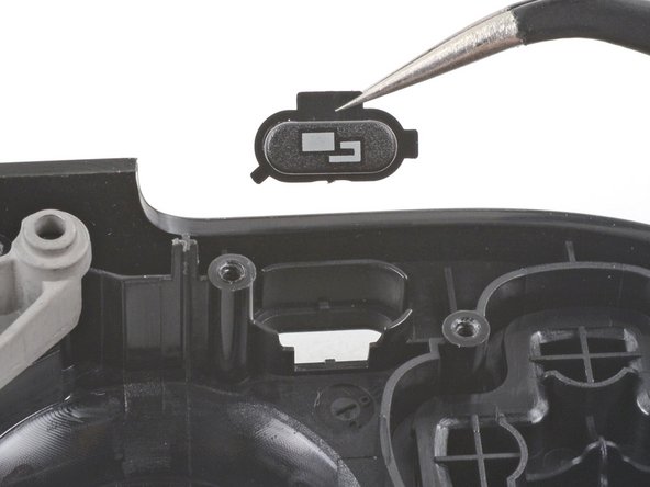
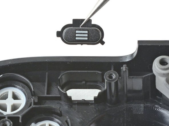
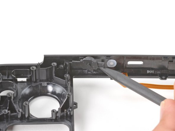
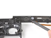
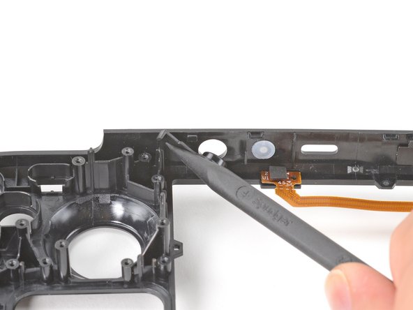
Use the pointed end of a spudger to lift the rubber flap to the right of the power button up and out of its plastic clip.
-
-
-
Use the pointed end of a spudger to lift the rubber flap to the left of the power button up and out of its plastic clip.
-
Remove the power button.
-
-
-
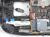
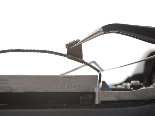
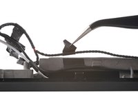
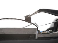
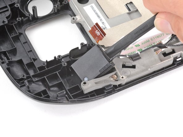
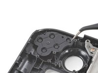
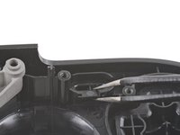
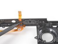
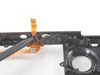
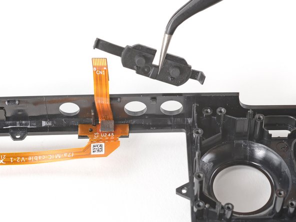
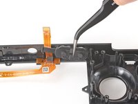
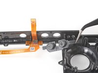
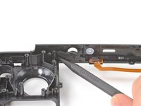
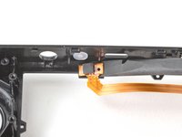
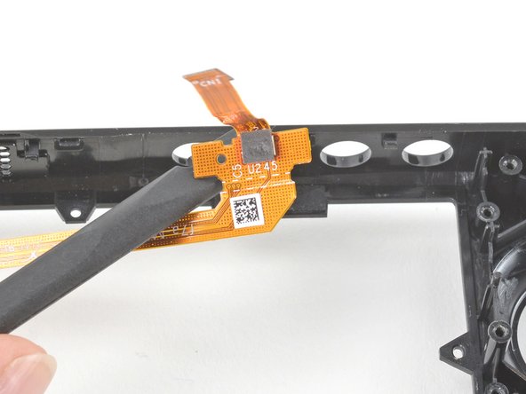
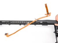
Insert the flat end of a spudger under the left end of the mic cable and pry upwards to peel it up from the front shell.
-
If the adhesive is stubborn, don't force the cable. Lightly heat the mic cable using an iOpener or a hair dryer to soften the adhesive.
-
-
-
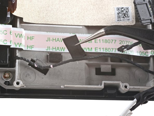
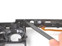
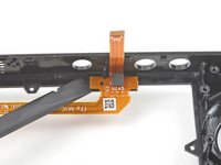
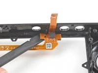
Insert the flat end of a spudger under the right end of the mic cable and pry upwards to peel it up from the front shell.
-
If the adhesive is stubborn, don't force the cable. Lightly heat the mic cable using an iOpener or a hair dryer to soften the adhesive.
-
-
-
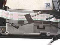
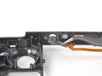
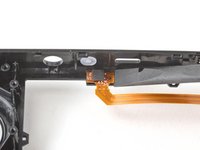
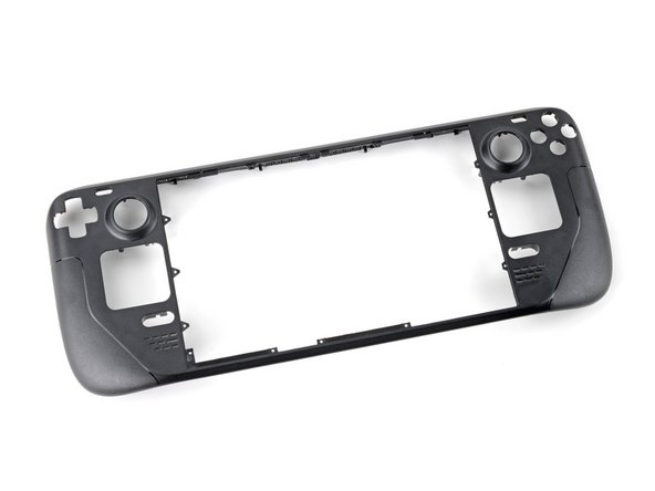
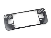
Remove the mic cable from the front shell.
-
Only the front shell remains.
-


To reassemble your device, follow these instructions in reverse order.
Take your e-waste to an R2 or e-Stewards certified recycler.
Repair didn’t go as planned? Try some basic troubleshooting, or ask our Steam Deck answers community for help.
Отменить: Я не выполнил это руководство.
24 человек успешно провели ремонт по этому руководству.


20 Комментарии к руководству
maybe I don’t need an Atomic Purple replacement shell…
Hahaha. Same
Same, wouldn't have minded a sweet water dipped or translucent outer shell. Bring back that mad catz/third party aesthetic.
I wanted to replace my old shell with a new one cause it got scratches... well, now I feel the scratches ain't that ugly.
Seems to me like a "Welp...I guess if I ever break the screen and have to replace it, that's when I'll get an atomic purple shell...